Intro to Circuit Diagrams
Nearly all of our experiments will use a circuit diagram to precisely express the circuit that will be built. Also referred to as schematics, or circuit schematics, we use them as an additional way to ensure we’re on the right track. Beyond that, learning how to read them is a very useful skill for all kinds of electrical projects down the line!
This article is intended to be used as a reference when reading circuit diagrams, keep it bookmarked somewhere handy if you think you’ll check back!
General Structure
Generally, circuit diagrams look a little like this:
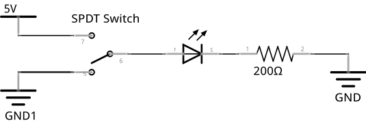
This is a circuit from one of our experiments, and it follows the gist of a circuit diagram: lines connecting symbols.
In a circuit diagram, any straight lines mean an electrical connection between things - no matter through a jumper, a wire, or a big metal plate, as long as electricity can flow. The various symbols represent the components that are being connected by the wires. We’ll cover the meaning of each symbol in detail below.
Light Emitting Diode
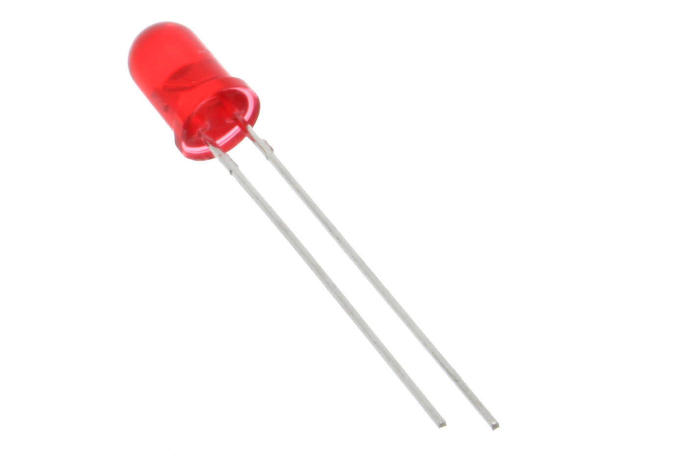
An LED is a component which lights up when powered.

Each LED has two terminals, denoted in the symbol as the flat and pointy ends of the triangle. This is because the LED is polar and the direction that it is oriented matters. The flat end is the ‘anode’ (+) and the pointy end is the ‘cathode’ (-), the triangle should always point toward ground, wherever it is.
Resistor
A resistor is a circuit element that converts electrical energy to heat.

Resistors have two non-polar terminals - meaning orientation doesn’t matter. The resistance across the terminals of a resistor is always within some percentage of the labelled value. Resistance is a measure of th ability of the resistor to convert electrical energy to heat. It’s unit is Ohms (Ω). The greater the Ohms, the more energy the resistor will siphon. The Ohm is an SI unit, so the ‘k’ (for kilo) prefix is used for numbers greater than 1000.
1000Ω = 1kΩ
Capacitor
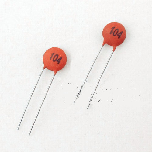
A capacitor is a component that blocks quick changes in voltage, but transmits constant voltages.

The capacitors in our kit have two non-polar terminals. They are used when we need to smooth out places where voltages can change rapidly. A capacitor’s ability to smooth out voltages is called its capacitance and is measured in Farads (F). Unfortunately Farads are not well scaled - 1F is a huge amount of capacitance. In these experiments we’ll be working with 0.0000001 Farads, or 100 nano Farads (nF).
Outside of our experiments, capacitors are found in filtering circuits making sure signals are sent correctly, without chatter.
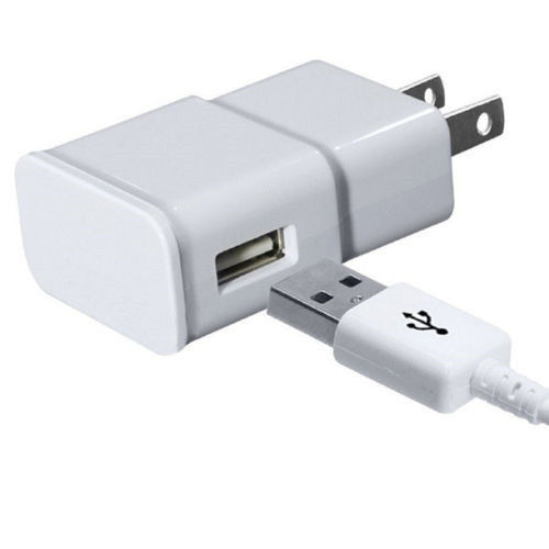
Power Supply
The power supply is the driving force in any circuit we build.
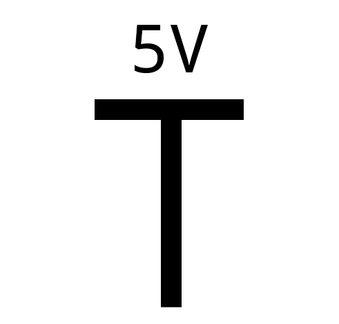
A power supply does as it is named - provides the power for our circuits to run. If we model electricity as a waterfall, the current is the amount of water flowing through, and the voltage is the height of the falls. The power supply is the source of both flow and height. The power supply is a ‘single’ terminal in most diagrams, however its other terminal is actually the ground terminal - just like waterfalls need the ground to reference how high they are.
Ground
The ground is the point of lowest energy in our circuit, all current will try to flow toward ground.

The ground is a single terminal symbol, and usually implies the GND pin on a Dock. In the circuits we’ll build, we will also make good use of the breadboards rails to connect many things to the same ground.
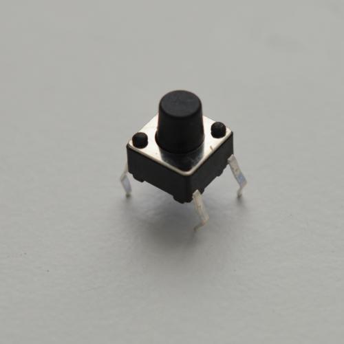
Push Button Switch
The push button switch is a single pole, single throw switch with four terminal pins switching one input to one output.

The push button switch has four terminals, connected to either side of the switch in pairs. Each pair is connected to each other, so the switch closes a single gap in the circuit. The ‘single pole’ refers to the single output connected to the two pins, while the ‘single throw’ refers to the single input connected to the other pair of pins.
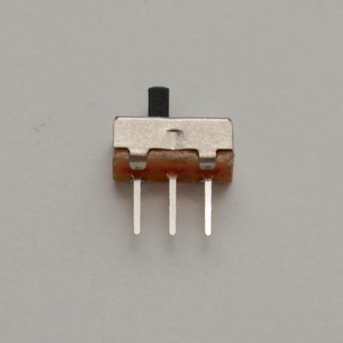
Switch - Single Pole, Double Throw
A single pole, double throw switch is a switch with two inputs that switch into one output.
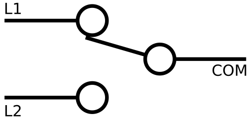
The switch has three terminals, one for each of the inputs (labelled L1, L2) and one for the output (labelled COM here). The inputs will never be connected, and one input is always exclusively connected to the output. This kind of switch is useful for logic circuits, because one input can reference logical HIGH and the other logical LOW without the ambiguity of open circuit.
The ‘single pole’ in SPDT refers to the only output, while the ‘double throw’ refers to the two exclusive inputs.
Integrated Chip (IC)
An integrated circuit (IC) is a small circuit built to be a modular component of larger circuits, with pins in and out depending on the layout of the circuit inside.
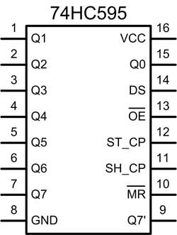
The integrate circuit can have many terminals. In our experiements that use ICs, we’ll go into more detail the purpose of the chip and what inputs and outputs are available.
The Expansion Headers
This symbol is used to denote a GPIO or other pin on an Omega Dock.

During our experiments, we’ll connect a multitude of circuits to the Omega. This symbol denotes a specific pin to which parts of the circuit should connect.
Devices
This symbol is used to denote the pins on devices like the keypad and seven segment display that don’t have ‘official’ symbols, but still need connections to and from.

These pins will always be labelled with the device that they represent. The pins themselves may not be laid out the same as the device’s pins, but all pins will be present.