Controlling Many LEDs
“We’ve blinked one LED sure, but what about a second LED?”
In this experiment, we’re going to use what we learned in the first experiment and wire up a bunch of LEDs. Then we’re gonna make some visual effects.
Building the Circuit
Let’s dive right into building our circuit. It’s going to be essentially the same thing as the first experiment, but repeated six times over!!
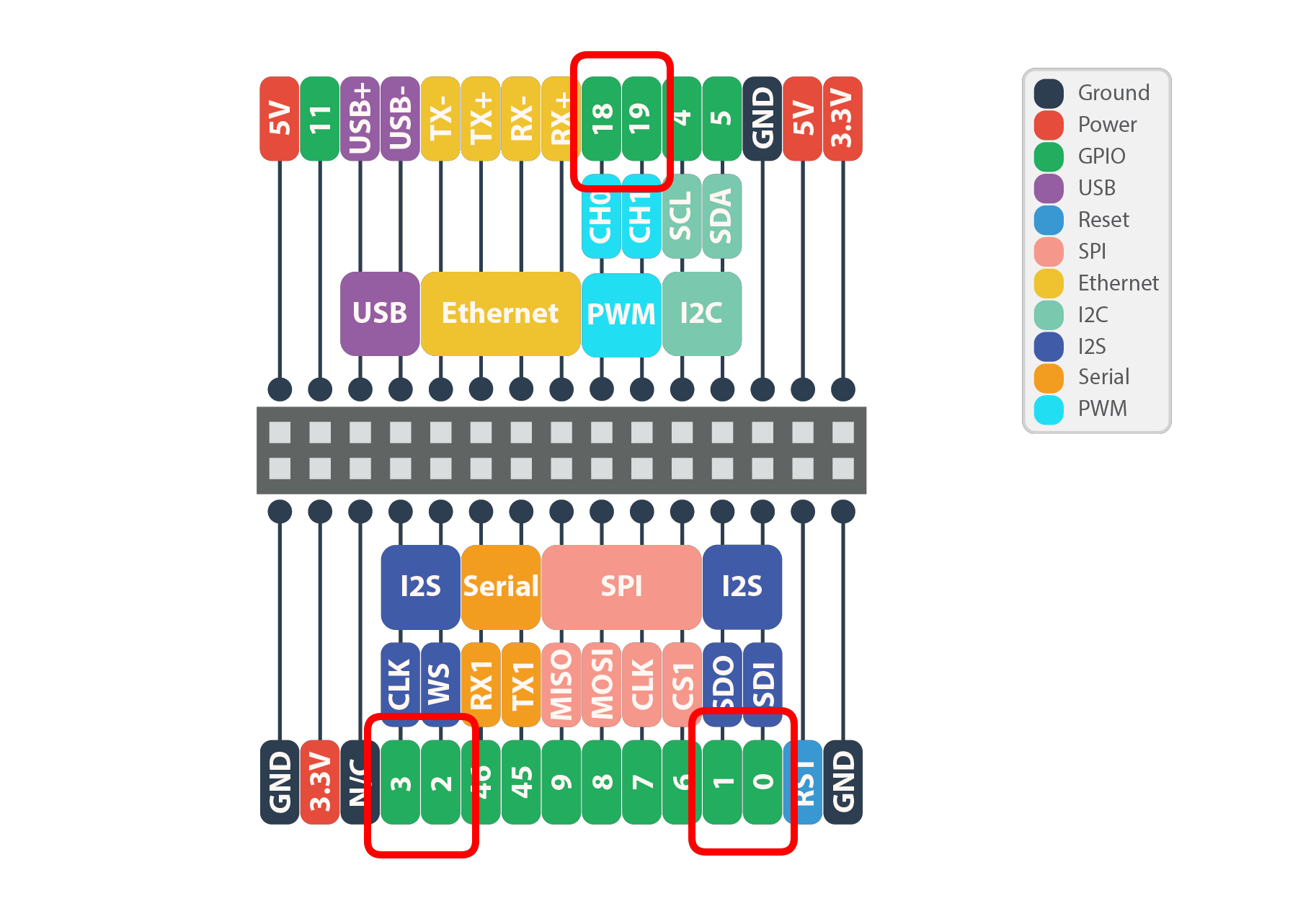
The GPIOs that are going to be used in this experiment are:
- 0
- 1
- 2
- 3
- 18
- 19
These have been highlighted in the image below:
What You’ll Need
We’ll be building a circuit on your breadboard using the following components:
- 1x Omega2 plugged into Expansion Dock
- 1x Breadboard
- 6x LEDs
- 7x Jumper Wires (M-M)
- 6x 200Ω Resisters
Hooking up the Components
While the individual LEDs will be connected in exactly the same way as in the first experiment, we’re going to be using the negative rail on the breadboard to make the wiring a little simpler.
Grab six LEDs and let’s do the following for each one:
- Plug in the LED across the breadboard, with the cathode on the left side of the gap and the anode on the right.
- Connect one end of a 200Ω resistor to the cathode row, and the other end to the negative rail marked
-on the left side of the board.
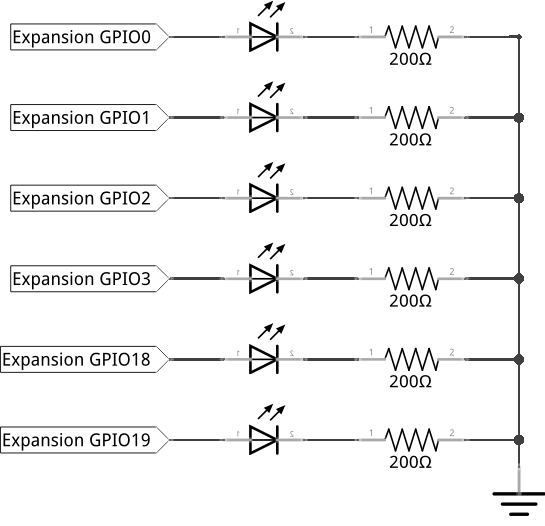
To finish off the circuit, we need to connect the anodes of our LEDs to GPIOs on the Omega using jumper wires. We’ll be using GPIOs 0, 1, 2, 3, 18, and 19 to control our six LEDs. To make our lives easy when writing the code to control the circuit, wire the top LED to GPIO0, the next one to GPIO1, and so on, with the bottom LED connected to GPIO19.
Now that you have all six LEDs plugged in, let’s connect a jumper wire from the - negative rail on the breadboard to a Ground pin on the Omega. Since this blue rail is connected vertically, we’ve just connected all of the LED cathodes to the Ground on the Omega using just one pin on the Expansion Dock!
Like previously mentioned, it’s just six copies of our first experiment connected to multiple GPIOs.
For reference, the circuit diagram for our first experiment looks like this:
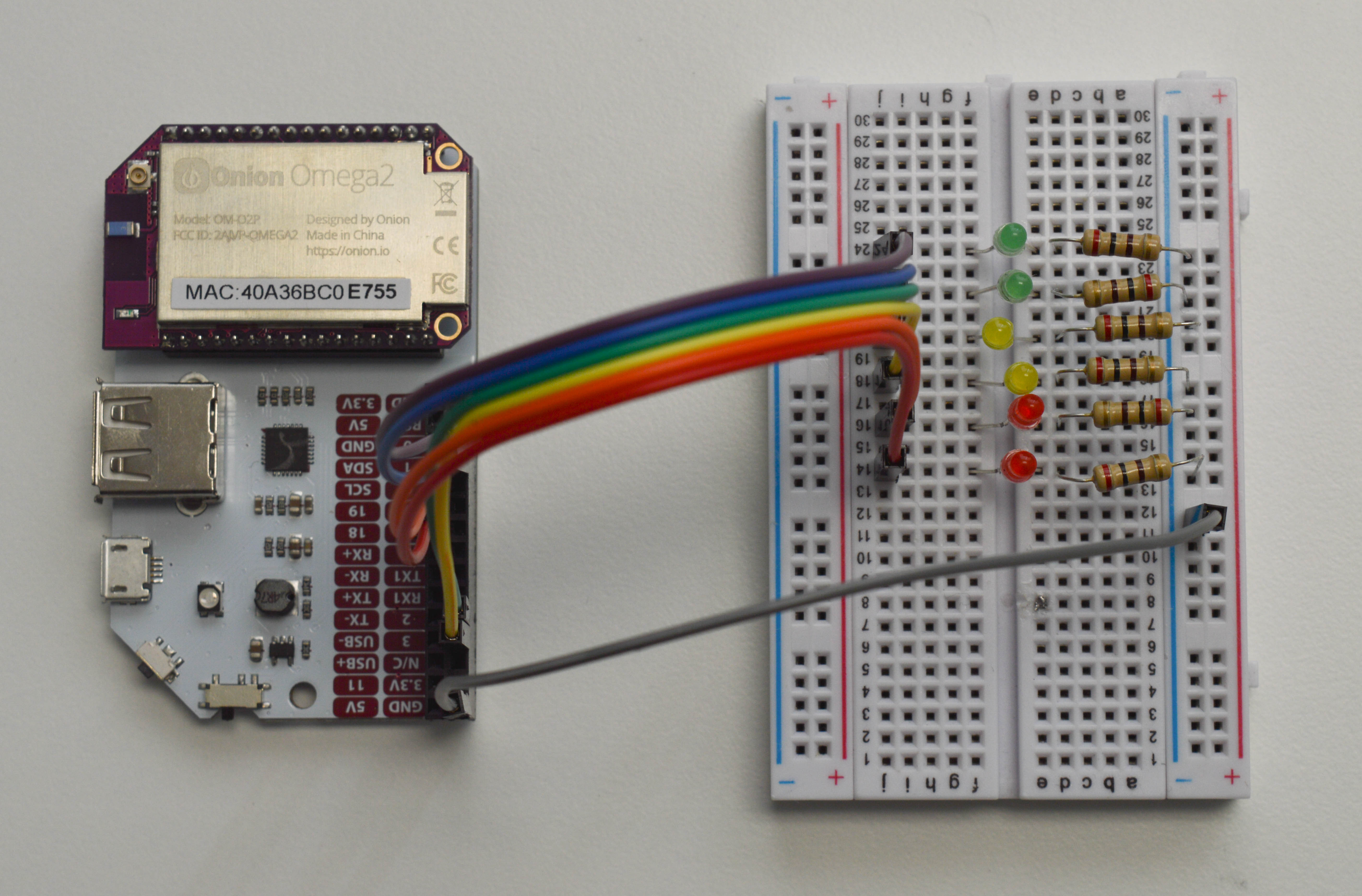
After assembly, your circuit should look something like this:
Writing the Code
Here’s where this experiment is different from the previous, the code we write will be significantly different since we now have five more LEDs to control. We’ll also be making a little animation instead of just blinking!
Create a new file STK02-lineUp.py to hold the code:
import onionGpio
import time

# specify sleep duration to be used in the program
sleepTime = 0.5

# create and populate a list to hold the GPIO pin numbers that control the LEDs
gpioPins = [0, 1, 2, 3, 18, 19]
# create an empty list that will hold the GPIO objects to control the LEDs
gpioObjects = []

# print which GPIOs are being used
print 'Using GPIOs:'
for gpioElement in gpioPins:
    print gpioElement

# populate the gpioObjects list
for gpioElement in gpioPins:
    # instantiate a GPIO object for this gpio pin
    ledObj = onionGpio.OnionGpio(gpioElement)
    # set to output direction with zero being the default value
    ledObj.setOutputDirection(0)
    # add the GPIO object to our list
    gpioObjects.append(ledObj)

# create a variable to hold the value of the LED
ledValue     = 1

# infinite loop - runs main program code continuously
while 1:
    # program all of the GPIOs to the ledValue
    for gpio in gpioObjects:
        gpio.setValue(ledValue)
        # pause after each LED is turned on or off
        time.sleep(sleepTime)

    # flip the value variable
    if ledValue == 1:
        ledValue = 0
    else:
        ledValue = 1
And run the code:
python STK02-lineUp.pyWhat to Expect
Your line-up of LEDs will be essentially chasing its tail: the left-most LED will turn on, and then the next one, and the next and so on. When all of them turn on, the left-most one will turn off, and the rest will follow suit.
This will repeat until you exit the program.
A Closer Look at the Code
This program looks pretty different from the code in the first experiment, but it does very similar things, just for six LEDs this time. Let’s take a look at some of the new stuff that was introduced.
Lists
The very first line of code after importing the modules is new to us: it’s creating a list.
A list is an ordered list of data, and a single piece of data in a list is called an element. We can access list elements by specifying an index number, and list indices start at 0. For example, calling on myArray[2] will return the 3rd member in the list.
Lists may be known as arrays in other languages. They are a very common structure used in programming and are very useful for collecting and organizing data in order.
Back to our code! The gpioPins list is meant to hold the GPIO pin numbers that control our LEDs, we populate (fill in) it with integers.
The gpioObjects list is a little different; we use it to hold six GPIO objects that will control the GPIOs to which our LEDs are connected. For now we will initialize it as an empty list; we will use a loop to populate it later.
For Loop
A for loop is used when you have code that needs to be repeated a known number of times. To loop, or iterate through items in a list, the generic syntax looks like this:
for element in someList:                  # a statement defining how many times to repeat (or a list to iterate through)
    # code to run using each element in someList
In our example, we want to print the numbers of each GPIO that we are using. We iterate through our gpioPins list by assigning each member to the gpioElement variable, then printing each one. We should see the following output:
Using GPIOs:
0
1
2
3
18
19
Lists of Objects
The second for loop in the program is used to populate the gpioObjects list with objects of the OnionGpio class with direction set to output. The loop will run for each of the elements in the gpioPins list, creating an object for each physical LED we’re using.
By the end of the for loop, the gpioObjects list contains six GPIO class objects, each set up to drive one of the GPIOs listed in the gpioPins list.
In our code, we use the for loop to interact with the list object by object, this is a pretty standard way of working with lists. An list of Ojbects works very similarly to lists of basic data types. By calling gpioObjects[n], you can interact directly with the Nth element of the list. List operations work the same way with objects as well.
For Loops Revisited
The very last for loop in the program will use the GPIO objects to turn the LEDs on or off to create our animation. It will iterate through all of GPIO class objects in the gpioObjects list and use them to set the associated GPIO to the value in the ledValue variable. The first time through it will turn our LEDs on one by one: it will first set GPIO0 to ledValue (which was initialized to 1), and then GPIO1, then GPIO2, GPIO3, GPIO18, and finally, GPIO19. The half second delay was added so the animation is actually visible by the human eye.
Similar to the previous experiment, the code that changes the LED states is in an infinite loop, so once the for loop is completed, the ledValue variable will be changed to hold the opposite value, and the for loop will be repeated, this time turning the LEDs off one by one. This cycle will continue, turning the LEDs on, and then off until the program is terminated.
Next we’ll learn how to fade an LED.