Dimming an LED
So far we’ve been turning LEDs fully on and fully off, but it’s also possible have LEDs dimmed to somewhere between on and off. And that’s what we’re going to do in this experiment: we’re going to use Pulse Width Modulation (PWM) to create a dimming effect on an LED.
Pulse Width Modulation
Pulse Width Modulation (PWM) is a technique of producing varying analog signals from a digital source.
Digital signals can only be either HIGH or LOW, where the HIGH voltage is some fixed value depending on the circuit. On the Omega, HIGH on the Omega is 3.3V.
On the other hand, an analog signal can be any voltage between HIGH and LOW. Normally, digital circuits can’t freely vary voltage signals, but they can use PWM to get close enough. It works by repeatedly pulsing a HIGH digital signal on and off so that the average voltage coming from the circuit over time would be equivalent to an analog signal between HIGH and LOW. To change the analog voltage, you can vary how fast the HIGH signal is pulsed.
There are some limitations to this method depending on how the driving circuit is built, but it’s relatively simple to implement and can be accurate enough for most cases.
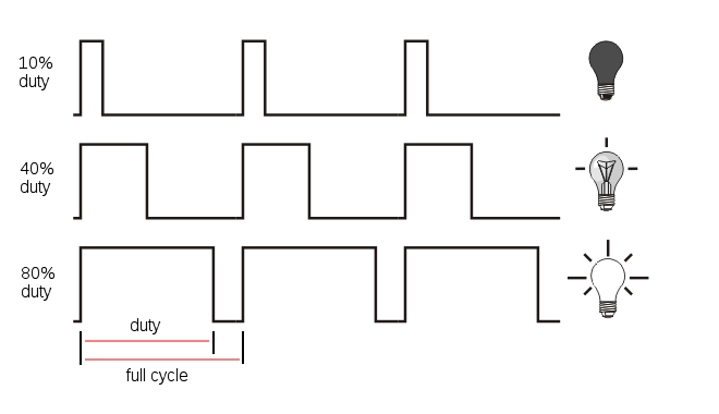
PWM and LEDs
By sending a PWM signal to an LED, we can control how bright that LED appears to shine. What’s actually going on is that the LED is turning on and off many, many times in a second. For example, if we send a 50% duty cycle PWM signal at 50 Hz to an LED, it will be on for 10ms, then be off for 10ms, then be on for 10ms and so on. You won’t actually see the LED turning on and off, instead you’ll see that the LED looks much dimmer than when you set the duty cycle to 100%.
Building the Circuit
We’re going to be providing power to the LED just like we did in the two previous experiments. The only difference is the speed at which we turn the LED on and off, and that will be taken care of in the software!
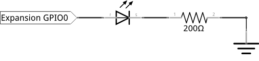
We’ll make the same LED circuit we used in the first experiment, so wire that back up. See the circuit diagram below:
What You’ll Need
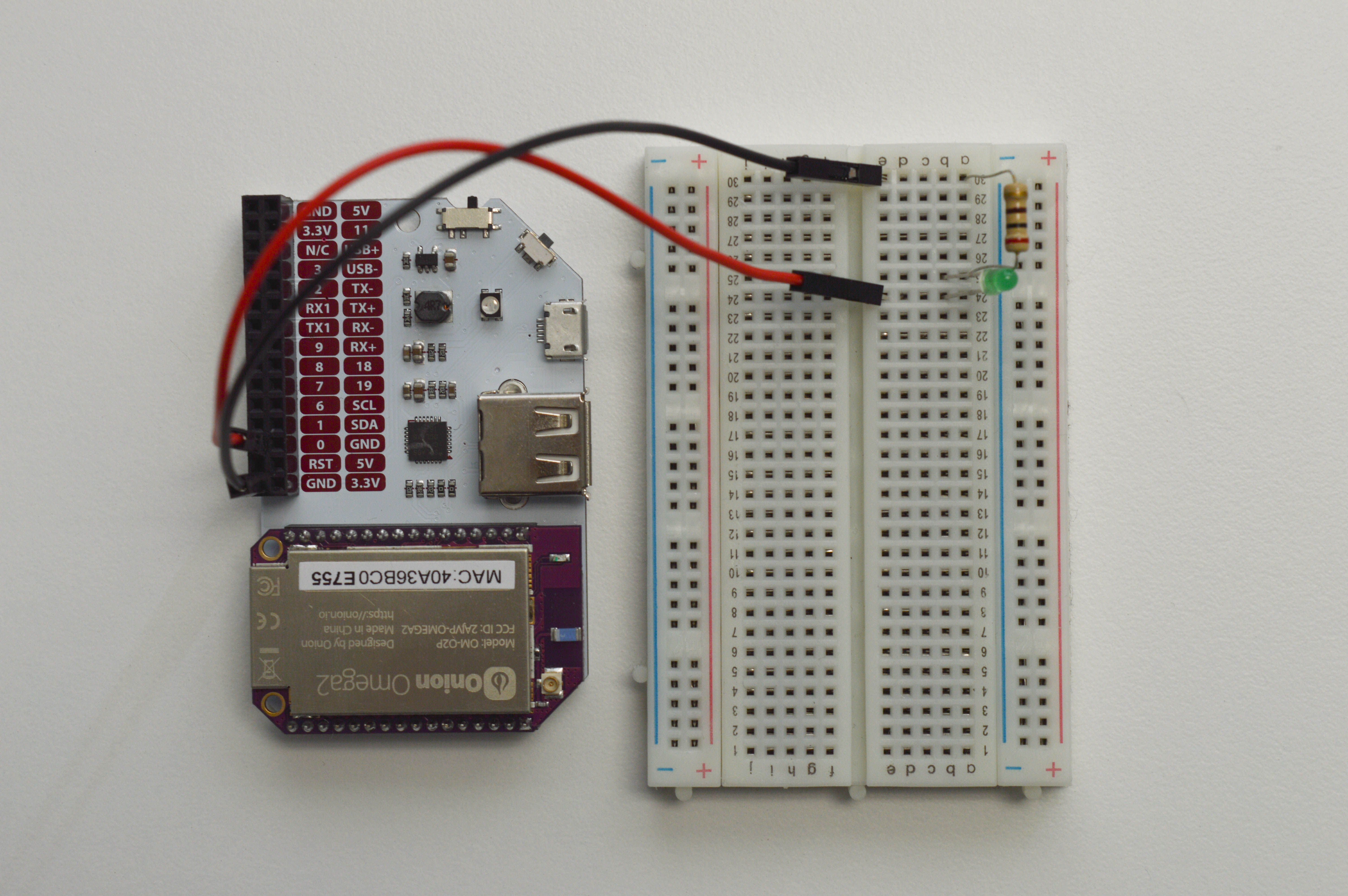
- Omega2 plugged into Expansion Dock
- 1x LED
- 2x M-M Jumper Wires
- 1x 200Ω Resistor
- Breadboard
Hooking up the Components
In this example we’ll only be fading a single LED, so go ahead and build the same LED circuit we used in the previous two experiments:
- Plug in the LED into the breadboard, make sure you plug the anode and cathode into different rows and that you know which is plugged where.
- Now connect one end of a 200Ω resistor to the the cathode row, and the other end to an empty row.
- Connect the other end of the resistor to a Ground pin on the Omega2.
- Let’s choose
GPIO0on the Omega2 to drive our LED, so connect a jumper wire fromGPIO0to the LED’s anode.
Your circuit should look like this:
Writing the Code
Let’s get to writing the main code. This time, we will be using fast-gpio, a utility we created to quickly control GPIO signals from the command line. However, we can also call this utility from within a Python script!
We’ll use the PWM functionality of fast-gpio to slowly increase the LED’s brightness by incrementing the duty cycle on its GPIO, then slowly decrease the brightness by decreasing the duty cycle. You’ll be seeing the light gently fade in and out.
See the Omega2 documentation for more info on fast-gpio.
Create a file called STK03-fading-led.py and paste the following code in it:
import time
import os

# specify sleep duration to be used in the program
sleepTime = 0.1

# define other program parameters
brightnessIncrement  = 2
dutyCycle = 0

# create a PWM signal using the fast-gpio system utility
def pwmLed(pin, frequency, dutyCyclePercentage):
    # create a string to hold our command line code,assign the function arguments to fast-gpio command arguments
    command = "fast-gpio pwm %d %d %d" % (pin, frequency, dutyCyclePercentage)
    # execute the command using the OS
    os.system(command)

# infinite loop - runs main program code continuously
while 1:
    # Increment the duty cycle by the brightnessIncrement
    dutyCycle=dutyCycle+brightnessIncrement

    # Assign GPIO 0 to the pwm duty cycle value
    pwmLed(0, 50, dutyCycle)

    # flip the value variable
    if (dutyCycle <= 0) or (dutyCycle >= 100):
        # Reverse direction at 0, and 100
        brightnessIncrement = -brightnessIncrement

    # make the program pause
    time.sleep(sleepTime)
What to Expect
When you run this script your LED will fade in and out. This is because we set the duty cycle to increase up to 100% (fade in to 100%), and then we begin to decrease the duty cycle down to 0% (fade out to 0%).
A Closer Look at the Code
The code this time is quite different from the previous two experiments. Instead of using Python classes and objects, we are calling a command-line program from within the script. We then wrapped this call in a Python function to make it easier to reuse.
In our infinite loop, we increment the duty cycle by the brightnessIncrement, and at 100% we reverse the value and decrement to 0.
Making OS Calls
fast-gpio works by setting GPIO registers directly on the processor and is a very fast process. It is fast enough that it can be used to generate PWM signals (this is known as software PWM).
In order to use fast-gpio, we need to use the os module. This module allows us to send command-line arguments in Python using os.system(command), where command is a string containing the arguments you would normally type in the terminal. This is known as a system call.
Functions
The system call to fast-gpio is powerful, but it has a lot of variable placeholders such as %d that we don’t want to be typing over and over again. So, we wrapped this unwieldy call into its own function in order to have a readable and much nicer Python interface for setting the PWM duty cycle. This function takes in the following arguments:
- GPIO pin number
- Frequency
- Duty cycle percentage
By doing this we make it really easy to reuse for other pins, frequencies, and duty cycle values.
Whenever you have problems that require identical commands to solve, it’s good practice to write your commands once in single functions that can be called wherever they are needed.
Next we’ll learn how to read a switch.