Using the Omega’s GPIOs
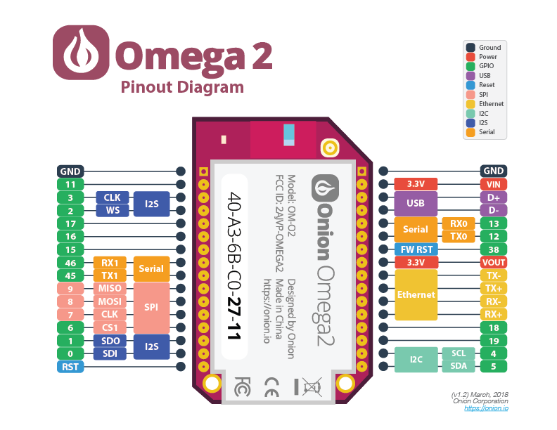
The Omega2 has twelve General Purpose Input/Output pins (commonly referred to as GPIOs) that can be fully controlled by you, the user. GPIO pins on most chips generally go unused, but on the Omega we can use these GPIOs to connect to, communicate with, and control external circuits.
On the Omega, we can control GPIO pins with a command-line tool known as gpioctl. This article will go through how gpioctl works, and the ways in which you can use it.
GPIO Electrical Ratings
The Omega2’s GPIOs are not 5V input tolerant!
See the table below for the GPIOs’ operating voltages:
| Parameter | Minimum (V) | Maximum (V) |
|---|---|---|
Input HIGH |
2.0 | 3.6 |
Input LOW |
-0.3 | 0.8 |
Output HIGH |
2.4 | 3.3 |
Output LOW |
— | 0.4 |
Warning: Connecting a signal to an input pin below the minimum LOW or above the maximum HIGH voltages may damage your Omega!
Standard 5V logic devices typically accept 3.3V as a logical HIGH, however, they output logical HIGH in the range of 4.4V to 5V. This means that the Omega can output to a 5V logical device, but input from the 5V logic device would damage the GPIO input circuitry.
Multiplexed Pins
A number of the available pins can be used for multiple purposes other than general purpose input/output when needed. Such pins are referred to as multiplexed pins. For example, the UART pins are designated as UART, but are multiplexed so that you can designate and use them as GPIO pins when you want. This is used to incorporate the largest number of protocol support in the smallest possible package.
You can use the omega2-ctrl tool to change the function of your pins.
To get the current mode of the Omega’s multiplexed pins, use the command:
omega2-ctrl gpiomux getand you’ll be given a list as a result:
root@Omega-2757:/# omega2-ctrl gpiomux get
Group i2c - [i2c] gpio
Group uart0 - [uart] gpio
Group uart1 - [uart] gpio
Group uart2 - [uart] gpio pwm
Group pwm0 - [pwm] gpio
Group pwm1 - [pwm] gpio
Group refclk - refclk [gpio]
Group spi_s - spi_s [gpio]
Group spi_cs1 - [spi_cs1] gpio refclk
Group i2s - i2s [gpio] pcm
Group ephy - [ephy] gpio
Group wled - wled [gpio]
The current mode for each group is indicated with the [].
Let’s examine the UART1 line:
Group uart1 - [uart] gpioHere we see the group is uart1, and the available modes are [uart] gpio, with the current mode being [uart].
Changing the Pin Function
To set a particular group of hardware pins to a specified mode, use the following command:
To illustrate the above, the following command will set UART1 pins to operate in GPIO mode:
omega2-ctrl gpiomux set uart1 gpioand running the get command from above to confirm our changes:
root@Omega-2757:/# omega2-ctrl gpiomux get
Group i2c - [i2c] gpio
Group uart0 - [uart] gpio
Group uart1 - uart [gpio]
Group uart2 - [uart] gpio pwm
Group pwm0 - [pwm] gpio
Group pwm1 - [pwm] gpio
Group refclk - refclk [gpio]
Group spi_s - spi_s [gpio]
Group spi_cs1 - [spi_cs1] gpio refclk
Group i2s - i2s [gpio] pcm
Group ephy - [ephy] gpio
Group wled - wled [gpio]
We see:
Group uart1 - uart [gpio]indicating that our change has indeed been applied.
Important & Special Pins
A few important notes on the Omega’s GPIOs, specifically:
Pins Important for Booting the Omega
There is a number of pins that affect the Omega’s Boot Sequence and require special attention. The pins fall into two categories:
- Pins that must be floating at boot time. They cannot be pulled up or pulled down, or else the Omega cannot boot
- Pins that must be floating or pulled down at boot time. They cannot be pulled up, or else the Omega cannot boot
| GPIO | Description | Boot Time |
|---|---|---|
| GPIO1 | GPIO / I2S SDO | Must be floating or pulled down |
| GPIO6 | SPI CS1/ GPIO | Must be floating |
| GPIO7 | SPI CLK | Must be floating |
| GPIO8 | SPI MOSI | Must be floating |
| GPIO12 | UART TX0 | Must be floating or pulled down |
| GPIO45 | UART TX1 / GPIO | Must be floating |
| GPIO36 | GPIO / PERST_N (Omega2S Only) | Must be floating |
Once the Omega has booted, these pins can be used normally.
SPI Pins & Onboard Flash Storage
The Omega’s processor communicates with the on-board flash storage using the SPI protocol. It’s configured as Chip Select 0 on the Omega’s SPI bus. Since there are two SPI Chip Select signals it’s possible to connect an additional SPI device to the Omega using Chip Select 1. As such, the SPI communication pins - CLK, MOSI, and MISO - are exposed on the Omega’s Expansion header as GPIOs 7, 8, and 9.
Since the Omega’s storage uses SPI, the SPI communication pins - GPIOs 7, 8, and 9 - must be used for the SPI protocol and cannot be used as regular GPIOs. If you wish to use these GPIOs, they are reserved for use only with SPI devices. These SPI devices will be use Chip Select 1 - GPIO6 - as their Chip Select signal on the Omega’s SPI bus.
To reiterate:
- GPIOs 7, 8, and 9 cannot be used as regular GPIOs - they must be used for the SPI bus
- Connecting non-SPI circuitry to these pins may prevent your Omega from booting or cause other damage to your unit.
- The SPI CS1 pin, GPIO 6, may be used to control an additional external SPI device
- The SPI CS1 pin, GPIO 6, may be still used as a regular GPIO when configured as a GPIO using
omega2-ctrl.
LED & Reset GPIOs
The Omega’s hardware design uses dedicated GPIOs to control the Omega’s LED and accept an incoming Reset signals:
| GPIO | Function | Exposed on Omega’s Headers? | Omega2S Pin Number |
|---|---|---|---|
| GPIO38 | FW_RST Active-High | Yes | 4 |
| - | HW_RST Active-Low | Yes | 5 |
| GPIO44 | Omega LED | No | 19 |
Pin Behaviour during Boot
Most of the Omega’s pins will remain at the default digital low state during the boot process. However, there are a few pins that will behave differently:
| GPIO | Omega2S Pin Number | Behavior |
|---|---|---|
| GPIO11 | 38 | Will settle at Digital High - Used to provide power for reset button on Omega2 Docks |
| GPIO14 to GPIO21 | 45 - 51 |
The behavior of these pins during boot is goverened by the Omega’s bootloader.
The Omega2 Bootloader is open source and can be found on GitHub: https://github.com/OnionIoT/omega2-bootloader
From the Command Line
The command-line tool gpioctl comes pre-installed on your Omega. gpioctl is based on setting file values inside the /sys/class/gpio directory. This is made possible with sysfs, a pseudo-file system that holds information about the Omega’s hardware in files, and lets the user control the hardware by editing the files.
The tool abstracts a lot of the more detailed commands from the user and simplifies them into easy-to-run commands that can control the GPIOs.
Using gpioctl
There are 7 options associated with gpioctl. The syntax of the command is as follows:
gpioctl <OPTION> <GPIO NUMBER>Here are some examples on how you can use gpioctl to interact with the Omega’s GPIOs.
Reading an Input
If you want your Omega to interface with a switch or button then you’ll need to use a GPIO to read the input of the switch.
To read an input of a GPIO we’ll need to first set the direction to input, connect an external circuit, and then read the value.
To set the direction of GPIO1 to input, enter the follow command:
root@Omega-2757:/# gpioctl dirin 1
Using gpio pin 1.
Now you’re ready to read from an external circuit!
Note: You will damage your Omega if your GPIO is set to output and you try to drive external current to the pin.
Let’s try reading GPIO1 with get:
root@Omega-2757:/# gpioctl get 1
Using gpio pin 1.
Pin 1 is LOW
Here we see that the GPIO pin is reading a digital LOW or 0.
Setting a Value
You can configure your GPIO pin to supply power to a load with your Omega, for example, if you were powering an LED.
We first set a GPIO pin’s direction via the dirout command:
root@Omega-2757:/# gpioctl dirout 1
Using gpio pin 1.
We then use the dirout-high option, which sets the GPIO to HIGH or 1:
root@Omega-2757:/# gpioctl dirout-high 1
Using gpio pin 1.
root@Omega-2757:/# gpioctl get 1
Using gpio pin 1.
Pin 1 is HIGH
Or we use the dirout-low option, which sets the value of the GPIO to LOW or 0:
root@Omega-2757:/# gpioctl dirout-low 1
Using gpio pin 1.
root@Omega-2757:/# gpioctl get 1
Using gpio pin 1.
Pin 1 is LOW
You can use the
gpioctl get <PIN>command to read a pin regardless of its direction.
Fast-GPIO
The fast-gpio command is similar to gpioctl in that it is used to control the Omega’s GPIOs. The difference is that while gpioctl worked by setting file values inside the /sys/class/gpio directory, fast-gpio works by setting GPIO registers directly on the processor and is inherently a faster process.
Command Usage:
For a print-out of the usage, run fast-gpio on the command line:
root@Omega-2757:/# fast-gpio
Usage:
 fast-gpio set-input <gpio>
 fast-gpio set-output <gpio>
 fast-gpio get-direction <gpio>
 fast-gpio read <gpio>
 fast-gpio set <gpio> <value: 0 or 1>
 fast-gpio pwm <gpio> <freq in Hz> <duty cycle percentage>
Setting a GPIO pin’s direction:
A pin can be configured to either be input or output.
To avoid damaging your Omega, set a pin to the input direction before driving any voltage to it!!
Reading a GPIO pin’s direction:
It may be handy to check a pin’s programmed direction before doing anything with it. The command to check a GPIO looks like the following:
For example, if GPIO 14 is set to output and 13 to input:
fast-gpio get-direction 14
> Get direction GPIO14: output
fast-gpio get-direction 13
> Get direction GPIO13: input
Reading a GPIO pin’s value:
You can read a pin’s value whether it’s in input or output mode.
fast-gpio read <gpio pin>For example, to read pin 14:
root@Omega-2757:/# fast-gpio read 14
> Read GPIO14: 0
Setting a GPIO pin’s value:
This will drive the selected pin to the value desired.
fast-gpio set <gpio pin number> <value to set; 0 or 1>If the pin is not in output mode, fast-gpio will silently change it to output before setting the value.
Generating a PWM signal on a GPIO:
Generate a software-based Pulse Width Modulated (PWM) signal on a selected pin. Specify the desired duty cycle and frequency of the PWM signal.
fast-gpio pwm <gpio> <freq in Hz> <duty cycle percentage>This will launch a background process that will generate the PWM signal.
Software-based PWM is implemented by a program that usually waits for a defined amount of time before toggling the GPIO output. This has the potential to be inaccurate since the CPU might be interrupted with other processes and tasks. Software PWM is generally good enough for dimming an LED but not for something requiring more accuracy, such as driving a servo.
To stop the PWM signal, set the GPIO’s value:
fast-gpio set <gpio> 0