Generating PWM signals
The Omega2 and Omega2S provide a number of ways to generate PWM signals.
The Omega module has a number of hardware PWM channels. The timing for these hardware based PWM channels will be highly accurate, however these hardware PWM channels are only available on specific pins. It is also possible to generate a PWM signal via a software application. Software PWM can use any GPIO pin but its accuracy is likely to be lower than the hardware PWM and signal timings can vary based upon system load.
External hardware such as the PWM Expansion Dock or other hardware based PWM ICs can be used to generate PWM signals.
Hardware Generated PWM Signals
The Omega’s SoC has a number of PWM modules. The Omega2 exposes two (2) PWM hardware modules on its pin headers while the Omega2S exposes all four (4).
The hardware PWM modules have a frequency range of 39Hz to 40MHz. For lower frequencies it is recommended to consider an external hardware PWM generator or the use of a software generated PWM signal from a GPIO pin.
Enabling PWM Pins
The Omega’s pins are multiplexed allowing the exposed pins to be used for a number of different functions.
| PWM Channel | GPIO | Pin | Notes |
|---|---|---|---|
| 0 | GPIO18 | ||
| 1 | GPIO19 | ||
| 2 | GPIO20 | 51 | Omega2S only |
| 3 | GPIO21 | 52 | Omega2S only |
The pin multiplexing configuration can be easily changed from the command line using omega2-ctrl.
For GPIO18:
omega2-ctrl gpiomux set pwm0 pwmFor GPIO19:
omega2-ctrl gpiomux set pwm1 pwmFor GPIO20:
omega2-ctrl gpiomux set uart2 pwm23For GPIO21:
omega2-ctrl gpiomux set uart2 pwm23This multiplexing configuration will need to be repeated after each reboot of the Omega.
Enabling PWM signals
Once the appropriate pins have been configured for PWM usage we can configure the PWM hardware module to generate the pwm signal using the following command:
onion pwm <CHANNEL> <DUTY CYCLE> <FREQUENCY>Where:
- CHANNEL is 0 (GPIO18), 1 (GPIO19), 2 (GPIO20), or 3 (GPIO21)
- Remember, Channels 2 & 3 are exposed on the Omega2S only
- DUTY_CYCLE is the percentage of time the signal is
ON, expressed 0-100 - FREQUENCY is the signal frequency, expressed in Hz
Stopping the PWM signal
It is possible to disable the PWM signal:
onion pwm <CHANNEL> disableExamples
For examples on using the onion command to generate PWM signals, see this blog post.
Software Generated PWM Signals
The fast-gpio utility can be used to generate a software-based PWM signal using a GPIO pin. See the Using the GPIOs article for full details on the fast-gpio utility.
Generating a Software-Based PWM Signal
Generate a software-based Pulse Width Modulated (PWM) signal on a selected pin. Specify the desired duty cycle and frequency of the PWM signal.
fast-gpio pwm <gpio> <freq in Hz> <duty cycle percentage>This will launch a background process that will generate the PWM signal.
Software-based PWM is implemented by a program that usually waits for a defined amount of time before toggling the GPIO output. This has the potential to be inaccurate since the CPU might be interrupted with other processes and tasks. Software PWM is generally good enough for dimming an LED but not for something requiring more accuracy, such as driving a servo.
To stop the PWM signal, set the GPIO’s value:
fast-gpio set <gpio> 0Expansion / external IC generated
The plug and play PWM Expansion provides 16 PWM channels generated by a dedicated hardware PWM IC that interfaces via I2C.
See Using PWM Expansion for details on the PWM expansion module.
Programmatic Hardware PWM
The Omega’s PWM modules are exposed on Linux via sysfs. The Linux kernel sysfs PWM interface provides a standardized way to expose PWM hardware for programmatic control from userspace applications.
You can find the PWM chip directories at:
/sys/class/pwmroot@Omega-C0FB:/# ls /sys/class/pwm
pwmchip0Configuring PWM via sysfs
In the pwmchip0 directory we find several files and directories:
# ls /sys/class/pwm/pwmchip0/
device     export     npwm       pwm0       subsystem  uevent     unexport
A brief description of each of these directories. More detail can be found in the Linux kernel sysfs PWM interface documentation:
device- Symlink to device information such as the device tree node, hardware device information etc.export- Write the PWM channel ascii character to this file to cause it to be accessible via sysfs, for example write ‘2’ to export channel 2npwm- File containing the number of PWM modules (4 for the Omega)subsystem- Symlink back to the sysfs directory of the class of this device, for example ‘/sys/class/pwm’ as this directory is for interacting with a pwmuevent- Used to register notifications for when devices are added, removed or other events occur.unexport- Opposite of ‘export’. Write the PWM channel ascii character to cause the file to be released from sysfs usage.
Sysfs Example
Here is an example of how to configure and enable a pwm PWM from the command line:
# cd /sys/class/pwm/pwmchip0
# ls
device     export     npwm       subsystem  uevent     unexport
# cat npwm
4
Note: npwm reports 4 channels which matches what we would expect from the Omega. Keep in mind that depending on your Omega module
there may be a limited number of PWM channels available. See the Omega pwm pin table for details.
For this example we will use channel 0.
First we want to configure the Omega pin muxing to enable the pwm function on the PWM channel 0 pin. Otherwise we could enable the PWM signal output but the signal would not be routed out of the chip and to the pin.
# omega2-ctrl gpiomux set pwm0 pwm
set gpiomux pwm0 -> pwm
Now lets tell the kernel that we want to be able to use sysfs to interact with PWM channel 0.
# echo 0 > exportAnd we can see that we now have a pwm0 directory:
# ls
device     export     npwm       pwm0       subsystem  uevent     unexport
Let’s configure pwm channel 0,
# cd pwm0
# ls
duty_cycle enable period polarity ueventduty_cycle- The time in nanoseconds when the PWM signal is assertedenable- Write0to disable PWM output,1to enableperiod- The time in nanoseconds of the entire PWM signalpolarity- Writenormalorinversedto control whether the asserted portion of the PWM signal is a logical high vs. a local low.uevent- Used to register notifications for device changes etc.
The nanosecond units allow for precise control of the PWM period and duty cycle. If we want to configure our PWM for a specific frequency we’ll have to perform some calculations to convert frequency to period.
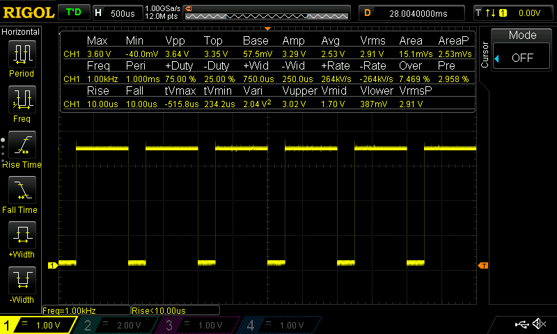
Let’s configure our PWM to output at 1kHz and a duty cycle of 75%.
period = 1 / frequency

1 / 1khz = 1 / 1000hz = 0.001s period

Converting seconds to nanoseconds,

0.001s * (1000000000ns/1s) = 1000000ns period
Knowing the period we can calculate the duration of the active portion of the signal, the duty cycle duration in nanoseconds, like:
duty cycle = 10000000ns period * 0.75 = 750000nsNow we can configure the pwm and enable it:
# echo 1000000 > period
# echo 750000 > duty_cycle
# echo 1 > enable
You should now be able to observe the 1kHz signal with 75% duty cycle on the pwm0 pin.
The PWM polarity setting is not currently supported by the Linux kernel mediatek pwm driver. It is possible to support signal inversion by setting the PWM duty cycle to its inverse. For example if the desired duty cycle was 20% but the signal was desired to be inverted, setting the duty cycle to 80%, 100% - 20% = 80%, will achieve the same result.
Golang example
Visit https://github.com/chmorgan/go-pwm-example for an example of controlling the hardware PWM modules from your own application. Through the use of golang, and its support of various architectures, it is possible to build and load this example onto your Omega2 module in a matter of minutes.