Blinking an LED
In our very first experiment, we will turn an LED on and off. This is the hardware equivalent of the ‘Hello World’ program. This first experiment will start small but it will be a solid foundation for the rest of the experiments.
Here’s a taste of what’s in store:
When inventing and building new things, try to break the work down into bite sized chunks, that way you’ll see progress much sooner and it will motivate you to keep going!
LEDs
Now let’s talk about Light Emitting Diodes, or as they’re more commonly known, LEDs. A regular diode is an electronic component that allows current to flow in only one direction. Think of it as a very strict policeman watching a one-way street. An LED is a type of diode that lights up when there is current flowing through it (but only when it’s flowing in the right direction)!
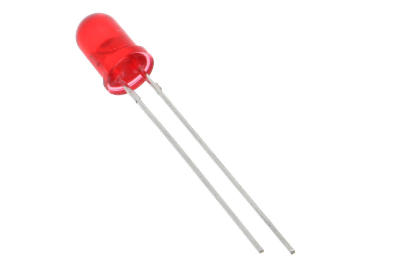
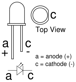
If you look closely, you’ll see that every LED has a longer leg and a shorter leg. This is because LEDs are diodes and we need to know in which direction it will allow current to flow.
- The longer leg is the positive side, called the anode. It should always be connected to the current source.
- The shorter leg is the negative side, called the cathode, where the current exits the LED. Always connect this side towards the ground connection.
Just like a regular light bulb, an LED can burn out if it’s supplied with too much current. LEDs in electronics are almost always used in series with a current limiting resistor that, you guessed it, will put a limit on how much current can pass through the LED.
For more information on how a resistor can limit current, we recommend checking out this Sparkfun tutorial on Ohm’s law
How to Build Circuits
Before we start building our experiment, let’s first go over some of the building blocks when it comes to experimenting with electronics.
Jumper Wires
We’ll be using jumper wires in all of our experiments and projects. They all work the same; connecting two points in a circuit together.
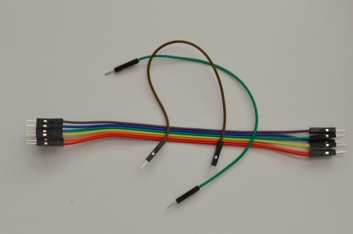
Jumper wires have ends that are either male or female. They both do the same thing, but the different ends make them work better in different situations.
Male ends are used to connect inputs and outputs that are enclosed in sockets - breadboards and the pins on the expansion docks are examples of where you’d need male jumper ends.
Female ends are able to connect to inputs and outputs that are true pins, for example on the PWM expansion, every wire that needs to be plugged into the PWM channels require a female end to work.
Depending on your needs, you can plug jumpers male to female to create longer jumpers, or to replace missing jumpers of a specific kind.
Breadboard
The breadboard is the foundation of all of the experiments we’re going to do together, and the starting-point for prototyping many electronics projects and even products!
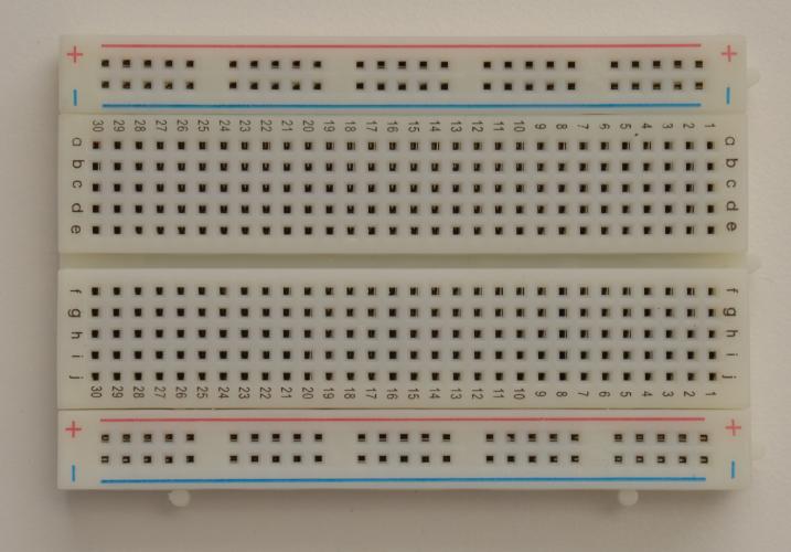
The breadboard’s sockets are connected to pieces of metal inside that are directly electrically connected (or “shorted”) to each other in a way to make it easy for you to build and prototype circuits.
The vertical columns labelled + and - that run along the sides of the breadboard are called the power rails. The sockets in each rail are shorted vertically. The + rail is commonly used for Vcc or power connections, and the - rail is typically used for ground.
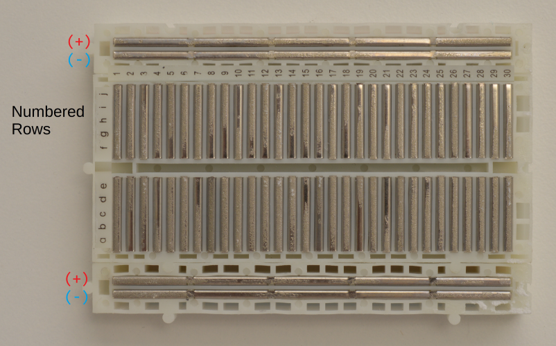
The sockets on the left and right side of the gap in the middle are called the terminal rows. In each row, the sockets marked a through e are shorted horizontally to each other, and same goes for the sockets f through j. When plugging integrating circuits (ICs) into the board, this lets you connect up to 4 wires per pin.
Last thing before we build - getting to know the Arduino Dock. The double-row headers beside the Omega and the three male pins near the OMEGA_RESET are pins connected to the Omega. The rest of the headers are connected to the ATmega Micro-Controller and have the same layout as that of an Arduino UNO. We will be using the ATmega pins mostly throughout these tutorials, with the Omega used to flash the chip and connect to the internet!
Building the Circuit
Now that we have an idea of what we’re going to accomplish, let’s get doing!
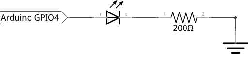
Here’s a diagram of the completed circuit for easy reference:
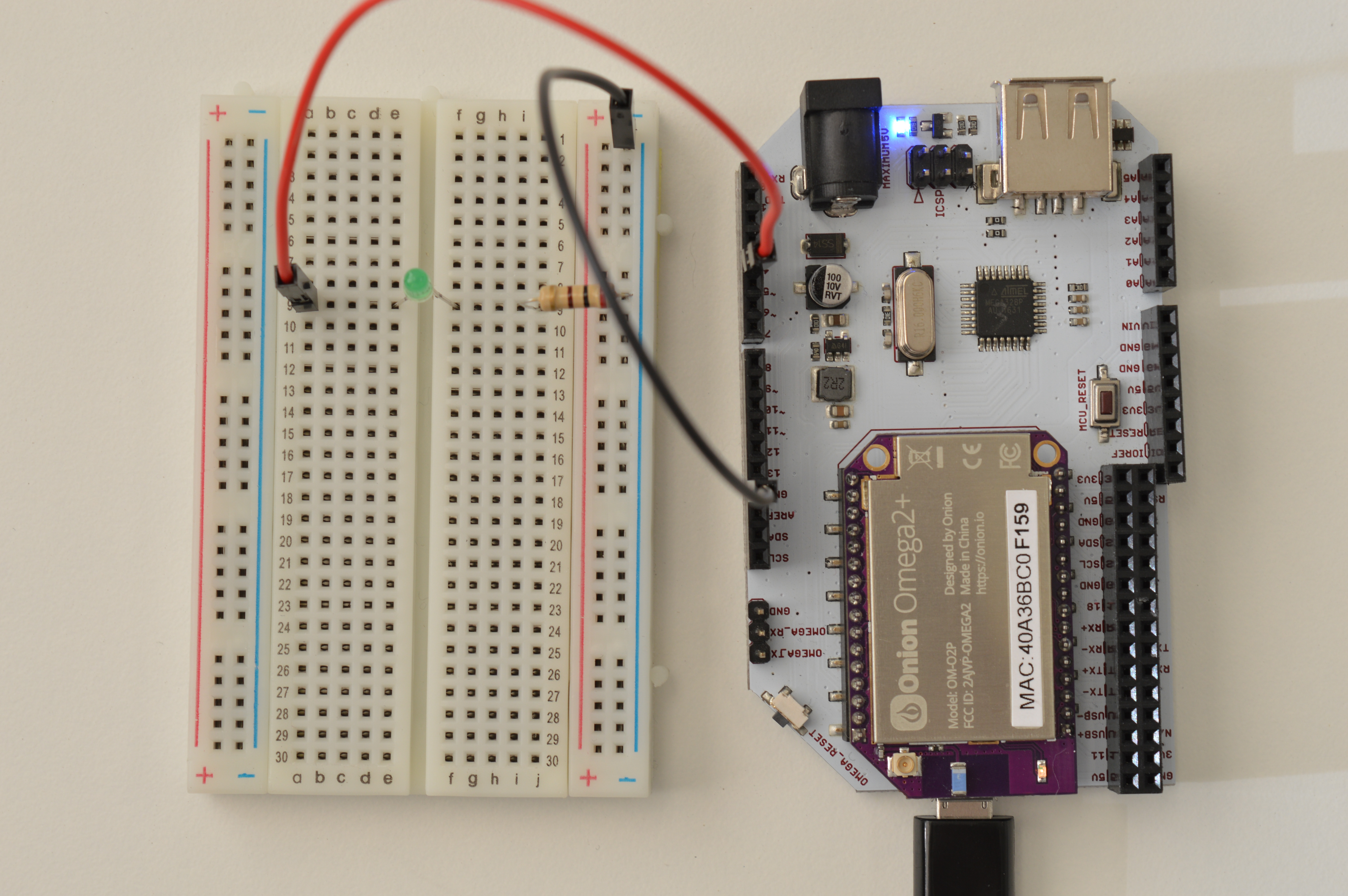
What You’ll Need
Prepare the following components from your kit:
- Omega plugged into Arduino Dock
- USB Micro-B cable for power
- Breadboard
- 2x Jumper wires (M-M)
- 1x 200Ω Resistor
- 1x LED color of your choice!
Hooking up the Components
To hook up the circuit, we need to connect the LED to a GPIO, make sure the resistor is placed appropriately, close the circuit, and we’re done! Follow the steps below:
- Plug in the LED into the breadboard, make sure you plug the anode and cathode into different rows and that you know which is plugged where.
- Now connect one end of a 200Ω resistor to the the cathode row, and the other end to an empty row nreaby.
- Grab a jumper and connect one end to the row with just the resistor in it, the other end goes to a Ground (
GND) pin on the Arduino Dock. - Let’s choose digital pin
4on the Arduino Dock to drive our LED, so connect a jumper wire from pin4to the LED’s anode.
It should look something like this when it’s all set up:
Writing the Code
If you haven’t already done so, you’ll need to prepare your computer by following our guide to flashing sketches wirelessly to the Arduino Dock.
Then fire up the Arduino IDE on your computer and write the following:
// duration to keep the LED on/off in milliseconds
int blinkTime = 1000;
// We set a variable for the LED pin number as good practice -
//    we just need to change it here to change it everywhere in the program
int ledPin = 4;


// This code runs once when the program starts, and no more
void setup() {
    pinMode(ledPin, OUTPUT);
}


// The code in here will run continuously until we turn off the Arduino Dock
void loop() {
    // turn the LED on
    digitalWrite(ledPin, HIGH);
    // pause the program for the amount set by blinkTime
    delay(blinkTime);

    // turn the LED off
    digitalWrite(ledPin, LOW);
    // pause again
    delay(blinkTime);
}
Let’s save the code below as SKA01-blinkingLed.ino so you can revisit it!
What to Expect
After the ATmega Micro-Controller on your Arduino Dock has been successfully flashed, your LED should start blinking: it should turn on for a second, and then turn off for a second, repeating until you flash a new sketch on to it. If you press the MCU_RESET button, the program will stop and restart from the beginning.
A Closer Look at the Code
While this is a small program, there are quite a few things going on, let’s take a closer look. First let’s take a look at the typical format of an Arduino Sketch. We start by defining our variables. Then we put code that need to be run once at the very beginnig of the program inside the setup() function. This codeswill be the first to be ran. Lastly, we put the codes that repeats over and over again in the void loop() function.
For our example, we need two variables: one for the pin number the LED is attached to and other to define the duration of the blink. We want to only set the GPIO as output only once but blink the LED continuously.
Setting GPIOs to Output
A GPIO can be set as either an input or output pin. ATmega pins are set to input as default. Input pins are mainly used for reading the the state (ON and OFF) or voltage level from a sensor or button. Input pin are in high-impedance state, meaning a very small amount of current will be able to change its state between LOW and HIGH. For our application, we want our GPIO to supply more current so we have to set it as OUTPUT: pinMode(ledPin, OUTPUT). However, keep in mind that input pins can also supply a very small amount of current (very dim LED).
After we set the pin to output, we will use digitalWrite to set the pin either HIGH to turn on the LED or LOW to turn off the LED, as seen inside the loop().
Variable Scope
For this code, we declared our two variable (ledPin and blinkTime) at the beginning of the code outside of any function brackets {}. This means the variable is globally defined and can be used anywhere in the sketch. However, if we define a variable inside a function, we will only be able to use it inside that function. This is a concept known as scope.
For example let’s say we defined ledPin inside the setup() function like so:
// duration to keep the LED on/off in milliseconds
int blinkTime = 1000;

// This code runs once when the program starts, and no more
void setup() {
    // LED on pin 4
    int ledPin = 4;
    pinMode(ledPin, OUTPUT);
}

void loop(){
    ...
}
Then if we were to try to use ledPin in loop(), we will get a scope error when the code is compiled. The scope of a variable defines which part of the code it can be used.