Reading a Push Button
So far, our programs have been looping continuously without stopping. In this tutorial, we get it to stop and listen for once! We’ll be writing code that will patiently listen for an event, and perform an action only when it happens. We will still be using physical input to control our software, however this time instead of a trimpot we will be using a push button. Along the way, we’re also going to learn about bitwise operations.
Push Button Switches
A push button is a momentary switch, so unlike a slide switch where the change in the switch state (on or off) will be permanent, the change in a push button’s state will only last while the button is being pressed. It’s called a momentary switch because the change in state is only while the button is being pressed; when the button is released, the switch will turn off.
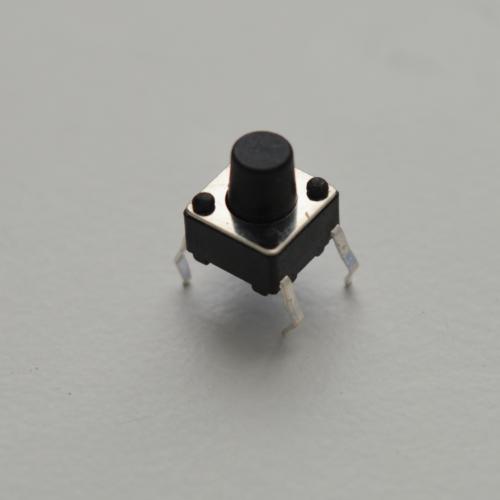
Unlike the SPDT switches with levers, the push button switches in your Kit are the single pole single throw type, or SPST. It’s named this way because:
- There is one contact that is switched when you push the button (“single pole”)
- The contact is switched between being disconnected and being connected to one output (“single throw”)
For example, the buttons on TV remotes are all momentary push button type switches, so expect the same type of functionality (changing settings) with push buttons in our experiments and projects.
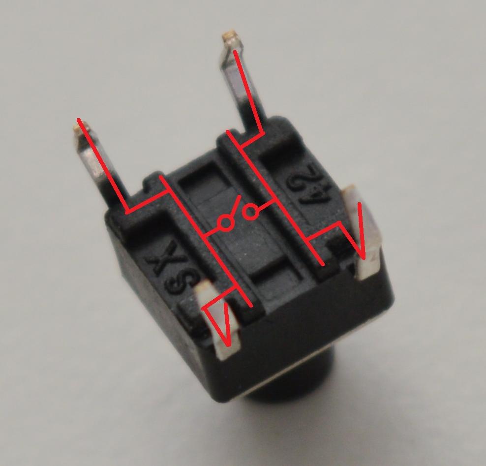
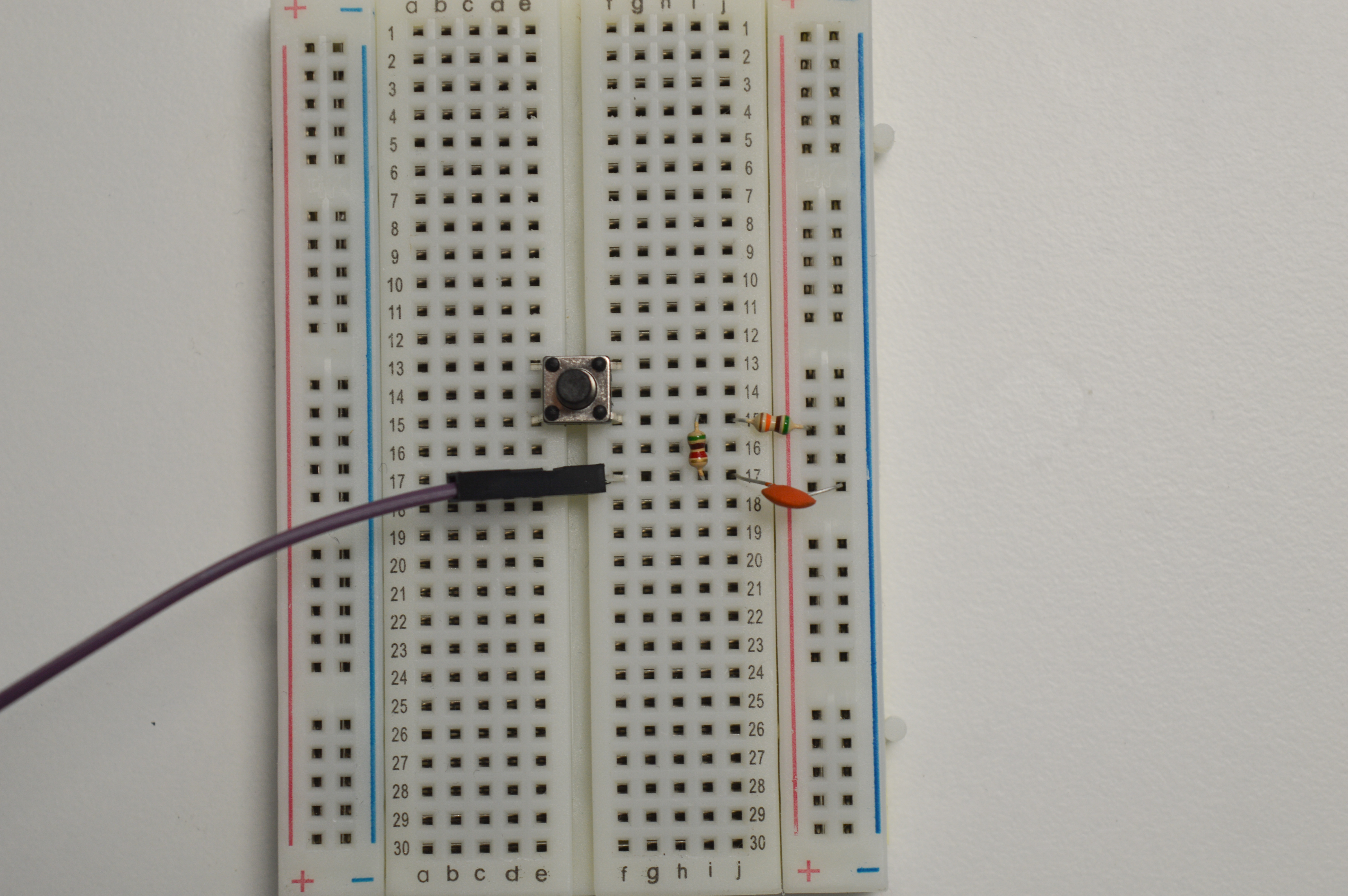
You may be wondering, “If there are four pins, how come this switch doesn’t have two switch contacts?” This is because the button is made of two pairs of connected pins that split each end into two connections. The photo below shows which pins are connected, so take note that your circuit properly switches when it’s supposed to:
Debouncing Switches
To simplify our circuits, we assume switches cleanly change state when you push or flip them. However, in real life with real physics, the electrical contacts of switches don’t work exactly the way we would like. When changing state, the electrical contacts will rapidly connect and disconnect like mini sparks as they just start to touch (when closing) or separate (when opening), until settling to their final value. This is known as bouncing. The graph below shows an example of a switch closing with respect to time: notice how the switch rapidly bounces betweeb OFF (low) to ON (high) repeatedly until settling at ON.
We want to avoid this since it will wreak havoc on our software that treats the button as a trigger for an action. When we press the button once, we expect the action to trigger only once; however, because the signal is bouncing, the action may be triggered tens or even hundreds of times. While this may not be an issue for simple actions such as turning on an LED, this can cause huge problems in more complex systems, such as programs that send messages to each other. For example, you don’t want to press a button to lower the thermostat by 1° and have it lower by 12!
Debouncing a Circuit
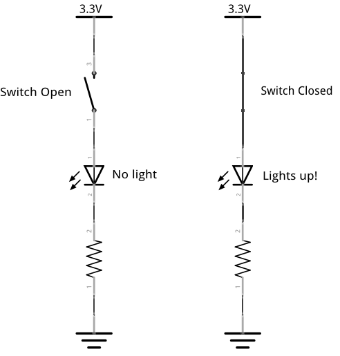
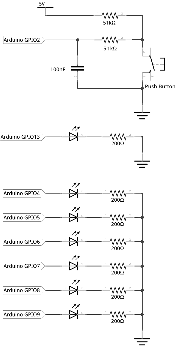
One way to solve this problem, or debounce the signal, is to add a few simple components around the switch to filter out these unwanted bounces. The diagram below shows a way of doing this.

Something to keep in mind about this setup is that the input reads HIGH when the switch is open, and LOW when the switch is closed. This may seem backwards at first, but this convention is actually very common with integrated circuits out in the wild! When writing programs, you should abstract this convention away from the main routines by using functions that return TRUE or FALSE depending on how you define the switch state, not the signal itself.
We’ve added 2 resistors, which limit the current (or charge flow) through the circuit, and a capacitor, which can store and release electrical charge. Here’s how it works:
Closing the Switch
- If the switch has been open for a while, the capacitor is fully charged and stores enough charge for a logic HIGH. The GPIO senses a logic
HIGH. - When you close the switch, the GPIO and capacitor are now connected to ground. The GPIO starts to be pulled LOW, but the contacts are bouncing and the signal is rapidly changing between HIGH and LOW.
- While the switch is bouncing, the capacitor starts slowly releasing its charge to ground through R2. The GPIO still senses a logic
HIGH. - When the switch is done debouncing, the capacitor quickly discharges the rest of its charge. The GPIO finally senses a logic
LOW.
Opening the Switch
- If the switch has been closed for a while, the capacitor is fully discharged. The GPIO senses a logic
LOW. - When you open the switch, the GPIO and capacitor are now connected to HIGH. The GPIO starts to be pulled HIGH, but the contacts are bouncing and the signal is rapidly changing between HIGH and LOW.
- While the switch is bouncing, the capacitor starts slowly charging through R1 and R2. The GPIO still senses a logic
LOW. - When the switch is done debouncing, the capacitor quickly completes charging. The GPIO finally senses a logic
LOW.
Resistor and Capacitor Values
When working with the Omega’s GPIOs and 3.3V HIGH signal, use the following components to build the debouncer:
| Component | Value |
|---|---|
| R1 | 50kΩ |
| R2 | 5kΩ |
| C | 100nF |
Add these to your switch circuitry to get rid of those pesky bounces!
Interrupts
An interrupt is a signal sent to a microprocessor or microcontroller through hardware or software that is an immediate trigger for a defined action. After the microprocessor has received the interrupt signal, it will stop what it is currently doing and will execute a function called the interrupt service routine (ISR). Once the ISR completes, the program will go back to executing what it was doing before the interrupt was received. When an interrupt is defined, both the trigger and the ISR need to be defined. For the interrupt trigger, first the source must be selected (in this case selection of the hardware pin to observe), and then the action to actually fire the interrupt. The possible trigger actions are:
- Rising - a change from logical low to logical high
- Falling - a change from logical high to logical low
- Both - any change in the signal
This is a powerful tool since we can use interrupts in our programs to perform an action only when a certain trigger is detected (like a button being pressed), while allowing the rest of the program to behave normally.
Building the Circuit
For this experiment we will start with the circuit from the multiple LEDs tutorial and add a push-button along with it’s debouncing circuit. The push-button will be connected to a ATmega pin which is capable of triggering external interrupts (only pin 2 or 3 for ATmega328). The push button will be used as input (either pressed or not pressed) and the LEDs will animate the the button presses
What You’ll Need
Prepare the following components from your kit:
- Omega plugged into Arduino Dock
- USB Micro-B cable for power
- Breadboard
- 10x Jumper wires (M-M)
- Resistors
- 6x 200Ω
- 1x 5.1kΩ
- 1x 51kΩ
- 1x 100nF Capacitor
- 6x LED color of your choice!
- 1x Tactile button
Hooking up the Components
- First, let’s setup the debouncing circuit:
- Connect one end of the 51kΩ resistor to one side of the switch. This can be either pin, but make sure you remember which side is which
- Connect the other end of the 51kΩ resistor to an empty row, this will be where we connect our voltage reference.
- Connect the end of the switch that is currently empty to the
GNDrail with a jumper; again, either pin will do. - Plug one end of the 5.1kΩ resistor to the same row where the switch and 51kΩ resistor are connected
- Plug the other end of the 5.1kΩ resistor to an empty row.
- Using the 100nF capacitor, connect the row where the 5.1kΩ resistor terminates to the
GNDrail.
- Connect the LEDs and resistors the same way as in the multiple LED tutorial.
- Plug in six LEDs onto the breadboard, each across the middle channel of the breadboard.
- Connect cathodes of the LEDs to the rail on the breadboard each through a different 200Ω current limiting resistor.
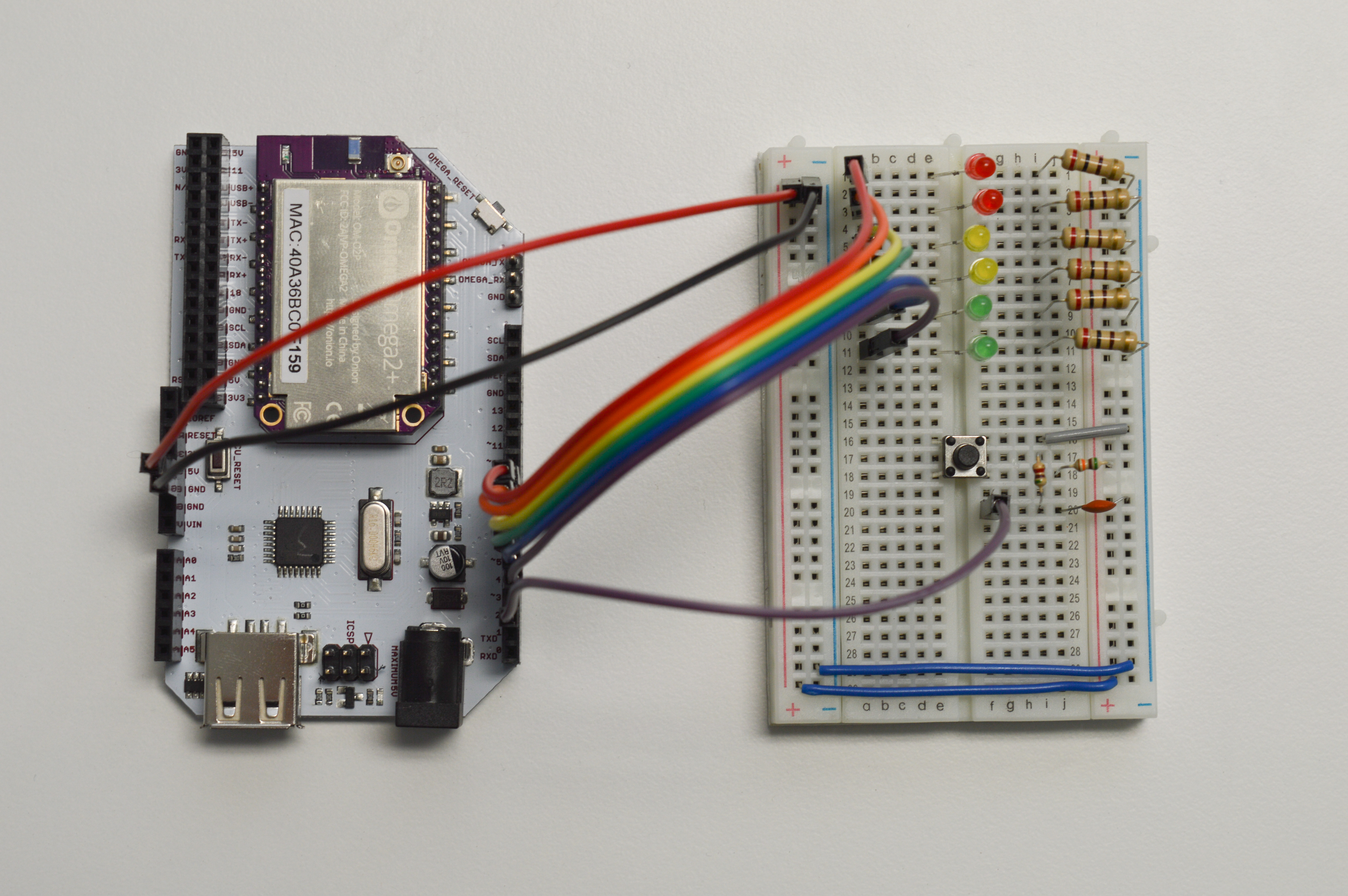
- Plug the push button onto the breadboard with the channel on the bottom of the button perpendicular to the channel on the breadboard. The circuit looks something like this:
Now let’s connect the circuit to the Dock:
- Connect the
GNDrail to aGNDpin on the Arduino Dock. - Connect the six anodes of LEDs (left to right) to six digital pins (
9,8,7,6,5,4) on the Arduino Dock (near the jack barrel connector). - From the debounce circuit, connect the row containing the 5.1kΩ resistor and the capacitor to GPIO pin
2of the Arduino Dock. - Finally, use a jumper wire to connect the other end of the 51kΩ resistor to
5Von Arduino Dock.
Writing the Code
The loop() part of this program only makes the LED flash on and off. The rest of the behavior is set to trigger on a hardware interrupt, meaning only when a signal on a pin changes state!
Copy the code below and flash it to give it a spin.
#define NUM_LEDS        6

// the pin number connected to the push button interrupt
int interruptPin = 2;
// an array of pins with LEDs attached
int ledPins[] = {9, 8, 7, 6, 5, 4};
// pin connected to the Arduino Dock LED
int statusLedPin = 13;
// a byte representing which LEDs are on
//    we're only using 6 of the 8 bits since we've connected 6 LEDs
volatile byte ledValues = B00000000;

// This code runs once when the program starts, and no more
void setup() {
  // initialize serial communication with the Omega
  Serial.begin(9600);

  // initialize the interrupt pin and set it to call setLED function only when the button is released (RISING edge trigger)
  attachInterrupt(digitalPinToInterrupt(interruptPin), setLedChain, RISING);

  // loop for initializing the LED GPIOs as output
  for (int thisPin = 0; thisPin < NUM_LEDS; thisPin++) {
    pinMode(ledPins[thisPin], OUTPUT);
  }

  // initialize the Arduino Dock LED GPIO to output
  pinMode(statusLedPin, OUTPUT);
}

// The code in here will run continuously until we turn off the Arduino Dock
void loop() {
    // blink the status LED
    digitalWrite(statusLedPin, HIGH);
    delay(1000);
    digitalWrite(statusLedPin, LOW);
    delay(1000);
}

// ISR for a button press
void setLedChain() {
    // decide whether enabling or disabling LEDs
    if ((ledValues >> (NUM_LEDS-1) ) & B00000001 == B00000001) {
        // the last LED is on, start disabling the LEDs
        //    shift all of the existing bits by 1, the least significant bit will be 0 (disabling the LED)
        ledValues = ledValues << 1;
    }
    else {
        // the last LED is not yet on, keep turning LEDs on
        //    shift all of the existing bits by 1, set the least significant bit to 1
        ledValues = (ledValues << 1) | B00000001;
    }

    // set all of the LEDs according to the ledValues byte
    for (int index = 0; index < NUM_LEDS; index++) {
        int value = (ledValues >> index) & B00000001;
        digitalWrite(ledPins[index], value);
    }

}
You know the drill, save it to SKA04-readingPushButton.ino, then get ready to press a button!
What to Expect
When the button is pressed, the left most LED should turn on. For each additional button press, another led will turn on, going from left to right. When all leds are on and the button is pressed, the LEDs will turn off one by one in the same order. All the while, the LED connected to GPIO13 will continue blinking steadily on and off.
Here’s the push button circuit in action:
A Closer Look at the Code
In this code, we wrote our main LED button function to execute on an interrupt instead of using polling as in the previous tutorial. We also use bitwise operations to work with binary numbers, whose digits can only be either 1 (HIGH) or 0 (LOW), to help us manipulate our LEDs more easily.
Interrupts
Interrupts are a different way of executing code. They are used to run code in response to an input event that could happen at any time.
To illustrate how interrupts work, let’s imagine you’re at home watching videos on YouTube; this is your loop() function. Suddenly the doorbell rings, it’s pizza delivery! You then do the following:
- Pause your current video, because you were interrupted by the arrival of food.
- The current program’s execution is paused at the moment the interrupt happens.
- Handle the interrupt by going to the front door, paying for the pizza, and carrying it back to your couch.
- The controller executes a specific function, such as
getPizza(), according to the interrupt condition and pin.
- The controller executes a specific function, such as
- Resume watching that funny cat video.
- The interrupt handler returns back to the program that was interrupted, which resumes where it was paused.
Since this method does not require the controller to repeatedly poll inputs, interrupts reduce the need for processor time and make your code easier to write.
In our code, we attach a interrupt to one of the pins using the built-in Arduino function attachInterrupt(). This function takes in three arguments:
- A digital pin that is setup to use interrupts using another built-in function
digitalPinToInterrupt(pin).- On the Arduino Dock, only pins 2 and 3 can be used for hardware interrupts.
- An interrupt service routine (ISR), or handler, which is a function to call when the interrupt triggers. In our example, we use
setLED().- ISRs should be short and fast, because other functions that use interrupts such as
delay()are disabled! - ISRs cannot return a value or data, as there is no specific place or function to return to.
- ISRs should be short and fast, because other functions that use interrupts such as
- An interrupt condition to trigger the ISR. We use
FALLINGbecause when the button is pressed, the signal goes fromHIGHtoLOW. However, the condition can be any of the following:- When a pin’s input signal changes:
RISING(LOWtoHIGH),FALLING(vice versa) - When a pin is a certain state:
LOW(HIGHis available on Arduino Due only)
- When a pin’s input signal changes:
Interrupts can also be attached to timers which will trigger an ISR every n microseconds. This method is not covered in this experiment, but you can find the details in the Arduino Timer documentation.
Binary Numbers
Binary numbers are numbers whose digits can only be 1 or 0. You can write a binary number in an Arduino sketch by adding a B in front of it, such as B00101001. See the below table for the first few binary numbers:
| Binary | Decimal |
|---|---|
| 000 | 0 |
| 001 | 1 |
| 010 | 2 |
| 011 | 3 |
| 100 | 4 |
| … | … |
and so on. The number of 0s in front of the number do not affect the number’s value.
Binary numbers with 8 digits are known as bytes. You can declare byte-type variables in Arduino if you want to limit their size to only 8 bits. In our case, that’s more than enough, so we declare a byte variable called ledValues.
Bits are typically numbered from right to left. Thus, the first bit of a number would be the one on the farthest right, the 2nd would be on its left, and so on.
For in-depth reference, check out this Bit Math in the Arduino Playground.
Bitwise Operations
In our case, we’re not interested in the decimal values of binary numbers, but in where the 1s and 0s appear. If we think of the 1s as HIGH signals and 0s as LOW, then a binary number can be used to represent the states of our LEDs!
We can manipulate these digits using bitwise operations. These operations compare the individual bits in two binary numbers. Let’s go through some examples in the code where they appear.
>> (and <<) - Bitshift
Bitshifting is moving the bits in a binary number left or right. The bitshift operators are << for shifting left, and >> for shifting right. To bitshift any binary number, specify the number of places to move. See the following example:
Bitshifting one place to the left is the same as multiplying the number by 2, and shifting to the right is the same as dividing by 2; remember that B0010 = 2, B0100 = 4, B1000 = 8, and so on. This is like how adding or removing zeroes in the decimal system is the same as multiplying or dividing by 10!
When shifting a number to the left, 0s are inserted from the right, and vice versa when shifting to the right.
& - Bitwise AND
Note: This is not the boolean AND, &&, which is used to evaluate true or false conditions.
If a particular bit is 1 in both of the two numbers, then the resulting number will also have a 1 in that bit; otherwise, it will be 0. For example:
B00010001 & B01110101 = B00010001This is typically used to check the values of individual bits. In the following if statement:
we are checking if the 6th bit (corresponding to the 6th LED) in ledValues is a 1 or not by shifting it all the way to the right and ANDing it with B00000001. If it is a 1, the operation will return a 1, and 0 for vice versa.
This operation is similar to multiplying two bits together. Think of it like asking, “Is this bit a 1 in either the first OR second number?”
| - Bitwise OR
This operator looks like an l, but is actually a straight vertical bar! You can typically enter it by pressing Shift-\ on most keyboards.
Note: This is not the boolean OR, ||, which is used to evaluate true or false conditions.
If a particular bit is 1 in either of the two numbers, then the resulting number will also have a 1 in that bit; otherwise, it will be 0. For example:
B00010001 | B01110101 = B01110101In the following line:
we are shifting ledValues to the left by one place, causing a 0 to appear in the first bit. We then OR it with B00000001, effectively “adding” a 1 to that bit. This process is repeated until all the LEDs are on.
This operation is similar to adding two bits, except that there is no “carry over” like in standard addition. Think of it like asking, “Is this bit a 1 in either the first OR second number?”
Program Sequence
The changes in ledValue as you press the button are summarized in the table below:
| Button Presses | ledValue |
|---|---|
| 0 | 00000000 |
| 1 | 00000001 |
| 2 | 00000011 |
| 3 | 00000111 |
| … | … |
| 6 | 00111111 |
| 7 | 01111110 |
| 8 | 11111100 |
| … | … |
| 12 | 11000000 |
| 13 | 10000001 |
| 14 | 00000011 |
| … | … |