Reading a Potentiometer
So far, we’ve been using a program to control output pins. Let’s try using physical user input to control our software! This experiment will use a potentiometer (trimpot) to control brightness of an LED. Along the way, we’ll learn about using polling to read the status of an input.
Before we begin, let’s take a look at the trimpot and one way to change the brightness of an LED.
Variable Resistor
We’ve worked with regular resistors before, and variable resistors do pretty much the same thing. The only difference here is we can change the resistance value of variable resistors. There’s many different ways they can operate - from dials to sliders and all sorts of in-between. They’re used as sensors, adjustors, and trigger mechanisms. For us, we’ll be using a dial based variable resistor called a potentiometer to act as an adjustment knob for an LED.
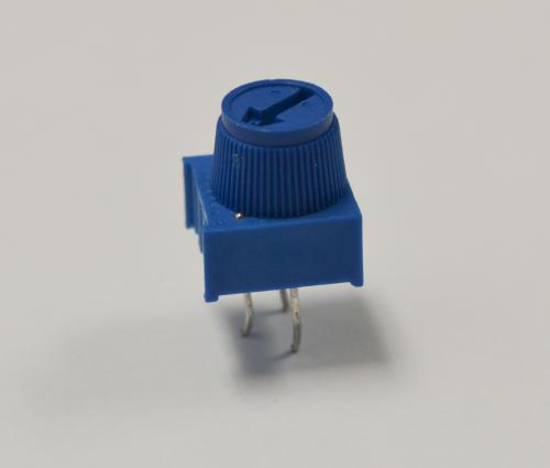
Potentiometer
The trimmer potentiometer, also known as a trimpot, is essentially two variable resistors (R1 and R2) connected in series. The total resistance of the two variable resistors (R1 + R2) will always be the same as the value of the trimpot, in our case 10KΩ. However, we can turn the knob on the trimpot to decrease the resistance of one resistor and at the same time increase the resistance of the other resistor. If we turn the knob to either end, one resistor will be 0Ω will the other one will be 10KΩ.
One variable resistor is between the left and middle pin of the trimpot while the other one is between the middle and right pin of the trimpot. If we connect the trimpot as a voltage divider as shown below, we will be able to vary the output voltage from 0V to the input voltage (5V) by simply turning the knob!

\[ V_{out} = \frac{R_1}{R_1 + R_2} \cdot V_{in} \]
If you’re curious to learn more about voltage dividers, Sparkfun has written a fantastic article going in-depth on how they work!
Dimming an LED
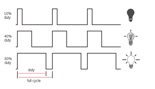
So far we’ve been turning LEDs fully on and fully off, but it’s also possible have LEDs dimmed to somewhere between on and off. This is accomplished by turning the LED on and off many times in a second, the brightness of the LED depends on how long the LED is allowed to remain on. That’s precisely what we’re going to do in this experiment: we’re going to use Pulse Width Modulation (PWM) to create a dimming effect on an LED.
Pulse Width Modulation
Pulse Width Modulation (PWM) is a technique of producing varying analog signals from a digital source.
Digital signals can only be either HIGH or LOW, where the HIGH voltage is some fixed value depending on the circuit. On the Omega, HIGH on the Omega is 3.3V.
On the other hand, an analog signal can be any voltage between HIGH and LOW. Normally, digital circuits can’t freely vary voltage signals, but they can use PWM to get close enough. It works by repeatedly pulsing a HIGH digital signal on and off so that the average voltage coming from the circuit over time would be equivalent to an analog signal between HIGH and LOW. To change the analog voltage, you can vary how fast the HIGH signal is pulsed.
There are some limitations to this method depending on how the driving circuit is built, but it’s relatively simple to implement and can be accurate enough for most cases.
Building the Circuit
For this experiment, we will use the knob of the trimpot (trimmer potentiometer) to control the brightness of the LED. We will connect a potentiometer to the analog input and an LED to a PWM pin with a current-limiting resistor. We’ll use the ATmega to interpret the input from the trimpot, and set the LED’s brightness accordingly.
Let’s take a more detailed look at the ATMega pins on the Arduino Dock since we’ll be using them mostly throughout these tutorials. Analog pins are from prefixed with capital A (A0 to A5). Pins 0 to 13 are digital pins. If there is a tilde sign ~ in front of the pin number, it means it can be used as a PWM pin. Pins 0 and 1 are serial pins and should not be used if we want to do serial communication between the ATmega and the Omega.
What You’ll Need
Prepare the following components from your kit:
- Omega plugged into Arduino Dock
- USB Micro-B cable for power
- Breadboard
- 5x Jumper wires (M-M)
- 1x 10KΩ Trimmer Potentiometer
- 1x 200Ω Resistor
- 1x LED color of your choice!
Hooking up the Components
We will be building the following circuit:
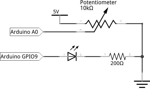
First, let’s set up the circuit:
- First plug the potentiometer on the breadboard with each of the three pins in a different row.
- Connect the left pin of the trimpot to the
GNDrail. - Pick two unused rows, then plug the LED across them, make sure to note where the cathode and anode are!
- Now connect the 200Ω resistor between the cathode row of the LED and the
GNDrail.
Now that the potentiometer and LED are set up, let’s connect them to the Arduino Dock so we can make them light up.
- With the connections to
GNDrail in place, let’s connect the rail toGNDon the Arduino Dock. - Using a jumper, connect the middle pin of the trimpot to the analog pin
A0on the Arduino Dock using a jumper wire. - Connect the anode of LED to the PWM pin
~9on the Arduino Dock. - Lastly, we’ll connect the right pin of the trimpot to
5Von the Arduino Dock as a reference for our input voltage.
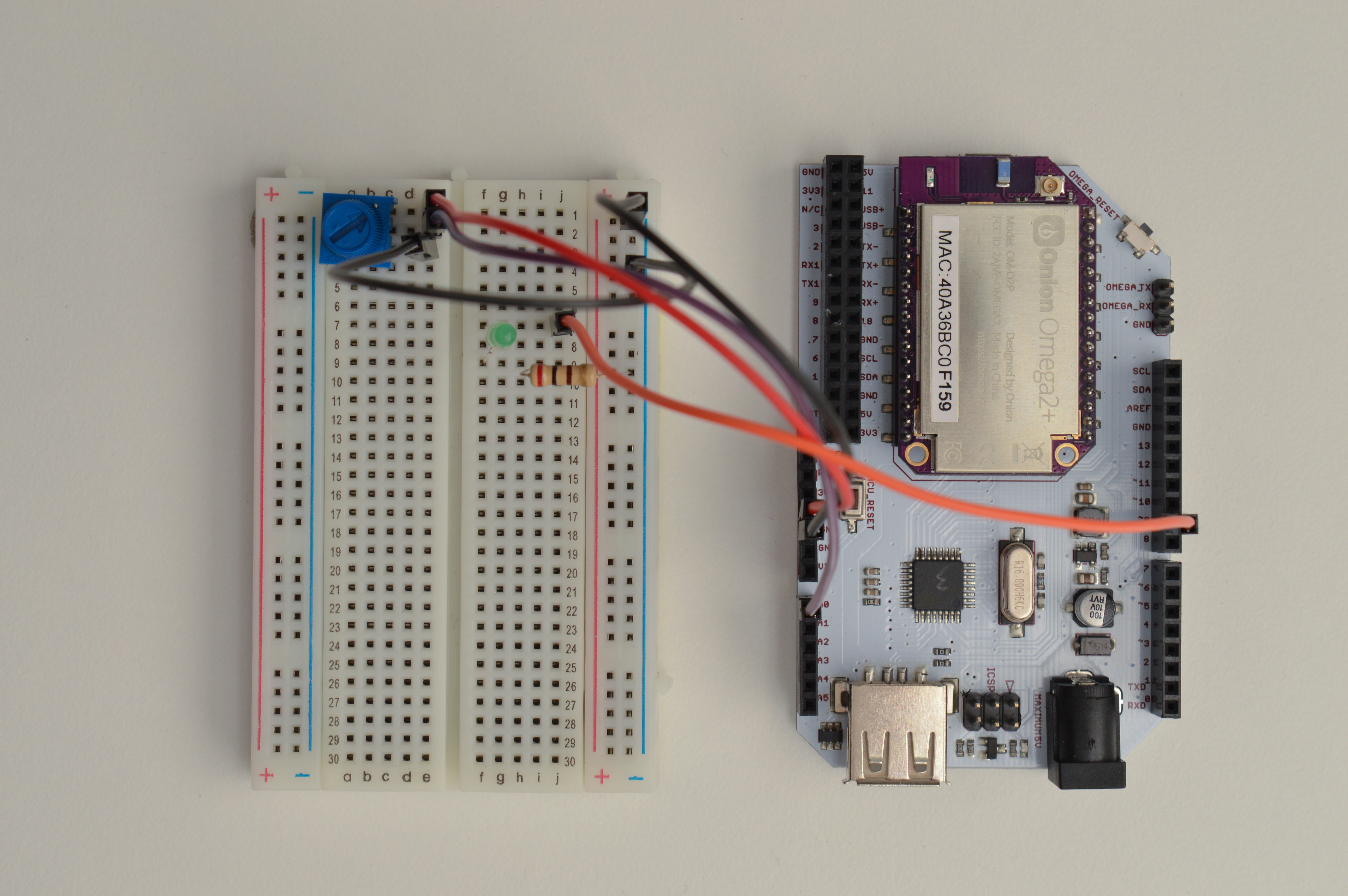
If all goes well, your circuit should work like this:
Writing the Code
The sketch we’ll write is going to set up two pins on the Arduino Dock - one to read the voltage from the trimpot, and the other to output a PWM signal to the LED.
Paste the code below into your IDE, and flash it over to your Arduino to see it in action!
// analog pin for reading the potentiometer value
int potPin = A0;
// pwm pin for setting LED brightness
int ledPin = 9;
// potentiometer output as a value between 0 and 1023
int potValue = 0;
// delay between sensor reads for stability
int readDelay = 100;

// code to be run once at the start of the program
void setup() {
  // initializing serial communication for sending potentiometer value to the Omega
  Serial.begin(9600);
  pinMode(ledPin, OUTPUT);
}

// read the potentiometer output as a value between 0 and 1023 and print it out to the Omega through serial
void readPotValue()
{
  potValue = analogRead(potPin);
  Serial.println(potValue);
  // delay between reads for stability
  delay(readDelay);
}

//use the potentiometer value to set the LED brightness using pwm duty cycle
void setLED()
{
  analogWrite(ledPin, potValue/4);
}

// continuously read the potentiometer and set the LED
void loop() {
  readPotValue();
  setLED();
}
As usual, we recommend saving the code in SKA03-readingTrimpot.ino so you can revisit it for reference.
What to Expect
When the code has been flashed on the ATmega, we will be able to adjust the brightness of the LED by turning the knob of the trimpot. This is because we can use the trimpot to set duty cycle to increase up to 100% (fade in to 100%), and then we begin to decrease the duty cycle down to 0% (fade out to 0%). In addition, we can use the following command line on our Omega to read the serial output of the ATmega:
cat /dev/ttyS1It will print a digital value (0 to 1023), which has been converted from the analog output of the potentiometer. This value should also correspond to the brightness of the LED. What is ttyS1? It’s actually the serial connection from the ATmega chip to the Omega! By reading the ‘file’, we can see the serial output from the ATmega chip through the Omega.
A Closer Look at the Code
In this code we introduced several new concepts: analog read and analog (PWM) write; whereas previously we were using digital write. In addition, we will introduce a concept called polling. Let’s take a look.
Analog Read
First we start by looking at the readPotValue() function, in which we use analogRead to get the output value of the potentiometer. The output of the potentiometer circuit is basically the output voltage of a voltage divider circuit. Since the input voltage is 5V, the output voltage will vary from 0V to 5V depending on the position of trimpot knob. The Arduino built-in function analogRead will convert that voltage (0-5V) to a digital value between 0 and 1023. Let’s store this value in the variable potValue for later use.
For analogRead to work we need to use one of the analog pins (A0 - A6) on the Arduino Dock. Moreover, analogRead takes in only one parameter, the pin number. Also notice that we do not need to set the pinMode of the pin reading the potentiometer to INPUT. This is because as mention earlier, the GPIOs are INPUT by default.
Analog (PWM) Write
Similar to previous tutorials, we set a pin output for light the LED. However this time, we will use a PWM (~) pin and instead of digitalWrite, we’ll use analogWrite. The name analogWrite might be confusing at first since we’re using PWM to power the LED. However, PWM is actually a form of digital-to-analog conversion. On the Arduino Dock, the output pins can really only output either ‘HIGH’ or ‘LOW’ as a voltage level. Analog output requires us to be able to output a wide range of voltages, but this is quite difficult and needs expensive components. So instead, we can do a form of analog output by pulsing the signal and using the percentage of time the signal is ‘HIGH’ as the analog output. This is the essense of PWM.
The Arduino built-in function analogWrite takes in two parameters: the pin number and a value representing the PWM duty cycle between 0 (always off) and 255 (always on). Notice this range (0 to 255) is about one fourth the range of the output from the analogRead (0 to 1023). So to do a quick conversion, we can take our variable potValue from before and divide by four to set the brightness of the LED.
Polling
Polling is the process of repeatedly checking an input. You may notice in the code there is a 0.1s delay in the readPotValue() function between reading the trimpot and the setting the LED. This delay was added for stability so that the CPU has some time to rest between every check on the LED. We don’t want to needlessly burden the CPU by constantly checking the same thing - remember that it runs incredibly fast!
Some of the issues during polling are as follows:
- You can’t do anything else in the program.
- You need to find a polling speed that balances the time delay and stress on the CPU.
If only there were a better way of doing this!