Reading a Key-Pad
In this experiment, we will make a circuit that can read input from a keypad. To make it more interesting, we’ll treat the input as a password such that if the correct password is entered, an LED will light up. The way we will build our circuit and accept input is very similar to the way computer keyboards work! When writing the code, we will also learn how to use Arduino libraries that are not preloaded by default.
Keypad
A keypad allows the user to press a button and the attached computer system will be able to tell which digit was pressed. If keypads were to use a pin for every button, there would be way too many data pins to connect! Instead, keypads only have pins for each horizontal row and pins for each vertical column. In our case we only need 7 (4 rows and 3 columns) instead of 15.
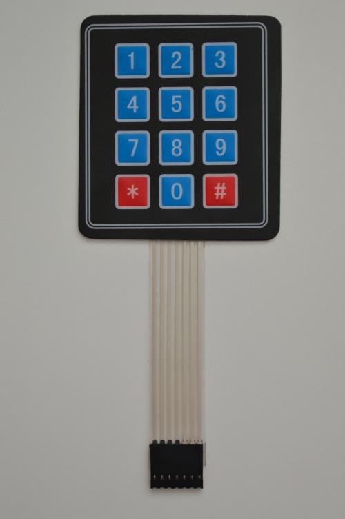
However, since the pins are not directly mapped to the buttons, our computer system will have to decode the signals coming from the keypad. When a button is pressed, the corresponding row and column pins will become logical high. So we will have to translate the row and column signal into the value of the button just like how chess positions are recorded.
Building the Circuit
For the circuit, we will need a keypad and some jumpers along with an LED to light up.
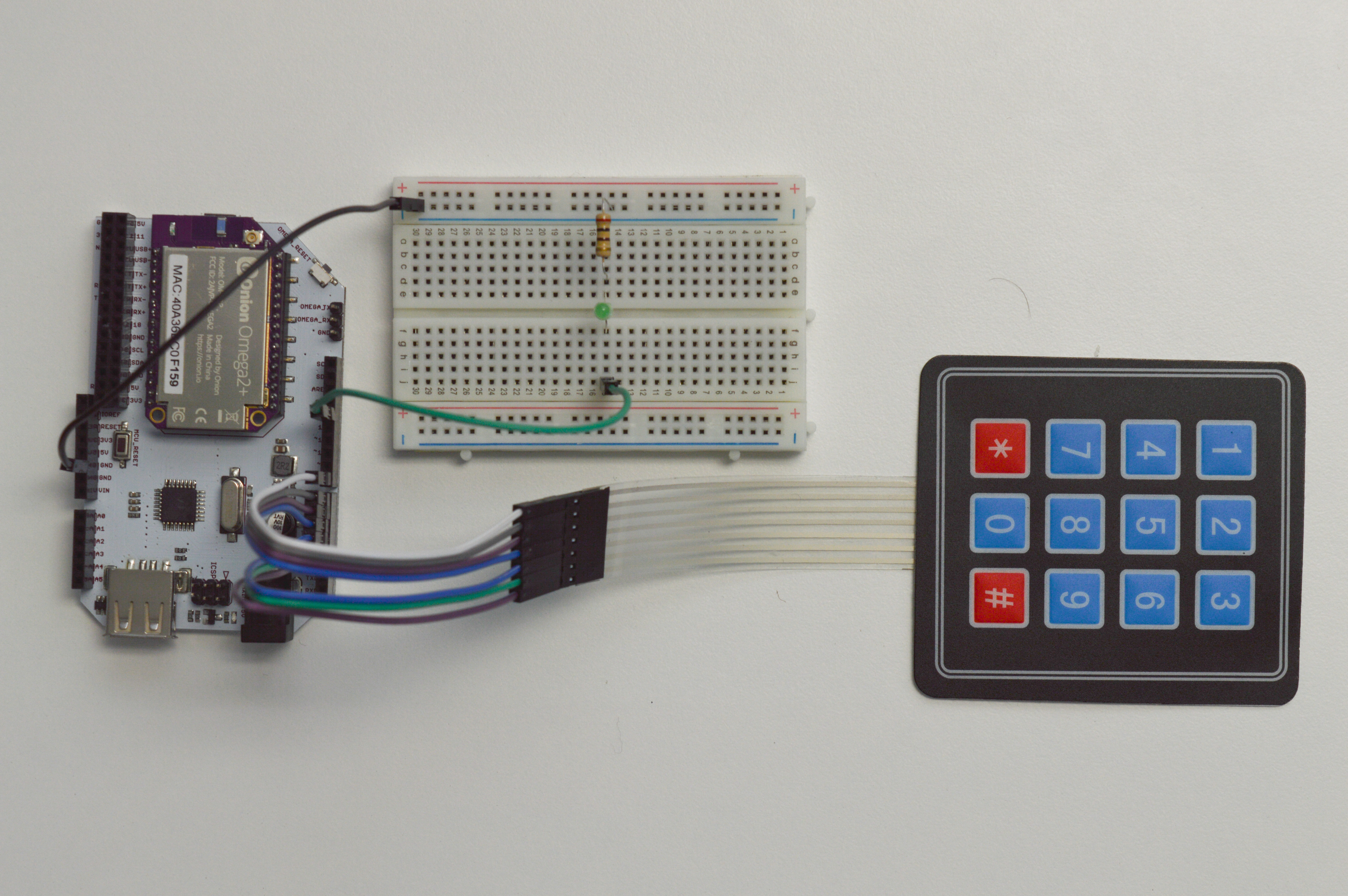
The keypad will connect directly to the Arduino Dock, and we’ll wire up the LED separate to be controlled by our code. For reference during the build, here’s a diagram of our circuit:
 #### What You’ll Need
Prepare the following components from your kit:
- Omega plugged into Arduino Dock
- USB Micro-B cable for power
- 1x Breadboard
- 15x male-to-male Jumper wires
- 1x 200Ω Resistor
- 1x LED of any colour
- 1x Keypad
Hooking Up the Components
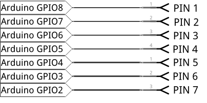
Once you have the components ready to go, we can begin putting it together. Keep in mind the keypad has seven pins, one for each row and column - not one pin per button.
- Connect all the seven keypad pins to the digital pins (
8,7,6,5,4,3,2) on the Arduino Dock in order from left to right, i.e. the left most keypad pin to pin8on the Arduino Dock. - Plug the LED in across the center of the breadboard, between whichever rows you wish.
- Plug the resistor between the
GNDrail and the row connected to the cathode of the LED. - Connect the
GNDrail to theGNDpin of the Arduino Dock with a M-M jumper - Use the last jumper to hook up the cathode row of the LED to pin
13of the Arduino Dock.
Writing the Code
This code will use a Keypad library which is probably not included in the Ardiuno IDE by default. There are two ways of getting ahold of the library and including it in our code. In the first way we can install it directly through the Arduino IDE:
On the Arduino IDE, click Sketch > Include Library > Manage Libraries. The Library Manager will show up; type keypad in the search bar and install the one titled ‘Keypad’.
The other way is to manually install a library.
- Download the Keypad library from a source: http://playground.arduino.cc/Code/Keypad#Download
- Move the unzipped Keypad file folder to the Arduino library folder: on Windows, its located at
C:\Program Files (x86)\Arduino\libraries- Linux -
~/Arduino/Libraries - MacOS -
~/Documents/Arduino/libraries
- Linux -
- Restart your IDE, and it should be useable in your sketches!
To use the library we need to #include it at the top of our code, by doing so, it tells the compiler to find the keypad library and drop all the code from it into the front of our sketch.
// include the Keypad library
#include <Keypad.h>

#define PASSWORD_LENGTH        4

#define STATE_INIT             0
#define STATE_IDLE             1
#define STATE_READ_INPUT       2
#define STATE_CHECK_INPUT      3
#define STATE_OPEN_SESAME      4

// variable to hold the current state
int state;

// four rows
const byte ROWS = 4;
//three columns
const byte COLS = 3;
// a 4x3 array of all the keys as chars
char keys[ROWS][COLS] = {
  {'1','2','3'},
  {'4','5','6'},
  {'7','8','9'},
  {'*','0','#'}
};

// connect to the row pinouts of the keypad
byte rowPins[ROWS] = {8, 7, 6, 5};
// connect to the column pinouts of the keypad
byte colPins[COLS] = {4, 3, 2};
// array of chars as password
char password[] = {'4', '3', '2', '1'};
// array of chars to hold our input
char inputKeys[PASSWORD_LENGTH];
// pin connected to LED that is to be lit up when password is correct
int ledPin = 13;
// variable used to index the password
int count;

// initializing keypad as an object from the Keypad library
Keypad keypadObject = Keypad( makeKeymap(keys), rowPins, colPins, ROWS, COLS );

// This code runs once when the program starts, and no more
void setup(){
  // initializing pin for the LED as output
  pinMode (ledPin, OUTPUT);

  // set the state to the inital state
  state     = STATE_INIT;

  // initializing serial communication with the Omega
  Serial.begin(9600);

}

// function to compare input character array against password character array
//    returns true or false based on if they're the same
bool passwordMatch(char inputKeys[]) {
    int i;
    for (i = 0; i < PASSWORD_LENGTH; i++) {
        if (inputKeys[i] != password[i]) {
            // if the current input character doesn't match the password, exit the loop
            break;
        }
    }

    // only if all of the input characters match the password will the loop run all the way through (and i will be PASSWORD_LENGTH)
    return (i == PASSWORD_LENGTH ? true : false);
}

// function to make decisions on changing the state based on the current state and input from the keypad
int stateDecisions(int currentState, char key) {
    int nextState = currentState;    // by default, stay in the current state

    switch (currentState) {
        case STATE_INIT:
            // print the info message and immediately advance to the idle state
            Serial.println("Please press # to enter the password");
            nextState = STATE_IDLE;
            break;
        case STATE_IDLE:
            // only advance to the reading input state if the # key has been entered
            if (key == '#') {
                // initialize variables used in the read input state
                count = 0;
                nextState = STATE_READ_INPUT;
                Serial.println("Enter the password");
            }
            else if (key != NO_KEY) {
                Serial.println("Come on, please press # to enter the password");
            }
            break;
        case STATE_READ_INPUT:
            if (key != NO_KEY) {
                // store the input key in our input array
                inputKeys[count] = key;
                count++;    // increment the number of inputs we've received

                // only advance to the next state if we've collected the same number of digits as the length of the password
                if (count == PASSWORD_LENGTH) {
                    nextState = STATE_CHECK_INPUT;
                }

                // print the key that was entered (for debugging purposes)
                Serial.println(key);
            }
             break;
        case STATE_CHECK_INPUT:
            // only if the input matches the password do we open sesame (advance to the password success state)
            if (passwordMatch(inputKeys) == true) {
                nextState = STATE_OPEN_SESAME;
            }
            else {
                Serial.println("Wrong password!");
                nextState = STATE_INIT;
            }
            break;
        case STATE_OPEN_SESAME:
            // execute the protected content
            passwordSuccess();
            // go back to the very beginning
            nextState = STATE_INIT;
            break;
        default:
            Serial.println("Wrong password!");
            break;
    }

    return nextState;
}

// code to run when successfully detected password
void passwordSuccess(){
    Serial.println("Correct password! LED On!");
     // turn the LED on
    digitalWrite (ledPin, HIGH);
    // keep it on for 3 seconds
    delay(3000);
    // turn the LED off again
    digitalWrite (ledPin, LOW);
}


// The code in here will run continuously until we turn off the Arduino Dock
void loop(){
  // turn the LED off
  digitalWrite (13, LOW);

  // read the entered key (as a char)
  char key = keypadObject.getKey();

  // find the next state based on the current state and input from the keypad
  state = stateDecisions(state, key);
}
What to Expect
Here’s the experiment running in our lab:
We will be using the keypad to create a password protected system. After the user presses the # key, they will be prompted via serial to enter a password. If the entered password matches with the password set in by char password[], which is 4321 by default, the blue LED on the Arduino Dock will light up for 3 seconds. If the wrong password has been entered, it will ask the user to press the # key again to retry.
A Closer Look at the Code
Here we modelled our code as a state machine to help us better organize our program’s behavior. We also made use of two-dimensional arrays to help us model our data to resemble our physical hardware more closely.
State Machines
State machines are a bit different from general purpose programs that we’ve been writing. They can be used when the possible situations, or states of the problem are all known and well-defined. In our case, we have only 5 distinct states that our controller can be in:
- Initialized
- Idle
- Reading input
- Checking input
- Open sesame! (running a password-protected function)
The state machine changes from one state to another in response to inputs such as pressing buttons on the keypad. These changes are known as transitions.
This also lets us have more organized program flow because states are free to transition wherever we want without us worrying about where they appear in the code. In our case, the STATE_CHECK_INPUT state can transition either to STATE_OPEN_SESAME if the password is correct, or to STATE_IDLE if the password is incorrect.
Two-Dimensional Arrays
Arrays can hold values of any type in order, but they can also contain other arrays. The dimension of an array is how many indexes you need to address a single member. In our case, we’re using two-dimensional arrays.
Two-dimensional arrays can be thought of as tables - with a fixed number of rows and columns, and each cell being a single element. Using a 2D array like a table, we can map the keypad directly to an array using X and Y coordinates. To get a better visual, let’s take a look at the code:
const byte ROWS = 4; //four rows
const byte COLS = 3; //three columns
char keys[ROWS][COLS] = {
  {'1','2','3'},
  {'4','5','6'},
  {'7','8','9'},
  {'*','0','#'}
};        // a 4x3 array of all the keys as chars
Our keypad does not have a pin for each button; instead, it has a pin for each row and column. When a button is pressed, the signals on the pin and column lines change, and the Keypad library is designed to detect these changes to determine which key is being pressed.
We use the keys[][] array to store the location and value of each button. Each button can be accessed by a pair of indices, kind of like X-Y coordinates. For example, we stored the ‘6’ key in keys[1][2].
We then use the Keypad.getKey() function that reads the column and row pins from the keypad, then finds the character in our array that corresponds to the button that was pressed. It goes through the following steps:
- Briefly scans for any buttons that were just pressed.
- If we pressed button ‘6’, it will detect pins
6and3.
- If we pressed button ‘6’, it will detect pins
- Converts the pin numbers into a row value and a column value.
- This will take
6and3and convert them to1and2respectively.
- This will take
- Returns the value of the button in our 2D array at the location specified by the row and column values.
- It returns the value of
keys[1][2], which is'6'.
- It returns the value of
This lets model our data to resemble our physical hardware more closely, which makes it easier to understand when writing our programs!
Going Further
In this experiment, we password protected an LED just to illustrate the concept. It would be a little more useful if the correct password triggered a different action, maybe moving a servo or actuating a lock? You can replace the contents of the passwordSuccess function to implement other password protected actions. Have fun!