Using a Buzzer
In this experiment, we’ll be sounding a buzzer from a button. Think of it as a model for your doorbell! We will build a circuit with a buzzer and a button, then we’ll cover two ways to get the buzzer buzzing: polling the input and using a interrupt. In the process, we’ll learn about the pros and cons of polling versus interrupts. As a required secondary superpower, we’ll use a switch debouncing circuit (the same one as in the push button experiment) to make sure our button presses come in clear.
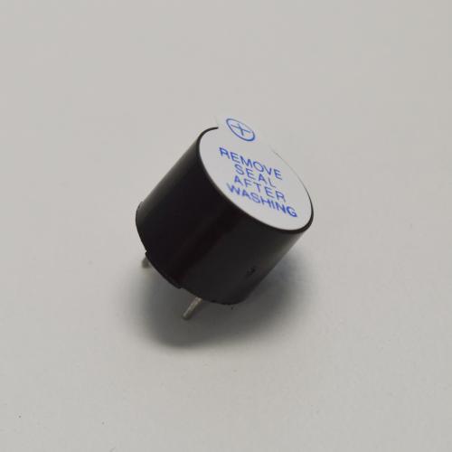
The Buzzer
A buzzer can be described as audio signaling device, an alternative way to describe it is an annoying sound device. It has two pins and if we connect the positive (marked with +) end to power and the other end (negative) to the ground through a current limiting resistor, it will make a (potentially annoying) buzzing sound. The buzzer which is included in our kit is electromagnetic: it uses electromagnetism to generate repetitive mechanical motion which creates the buzzing sound.
If we connect the positive end of the buzzer to a pin on our Arduino Dock, we can use software to control the buzzing!
Building the Circuit
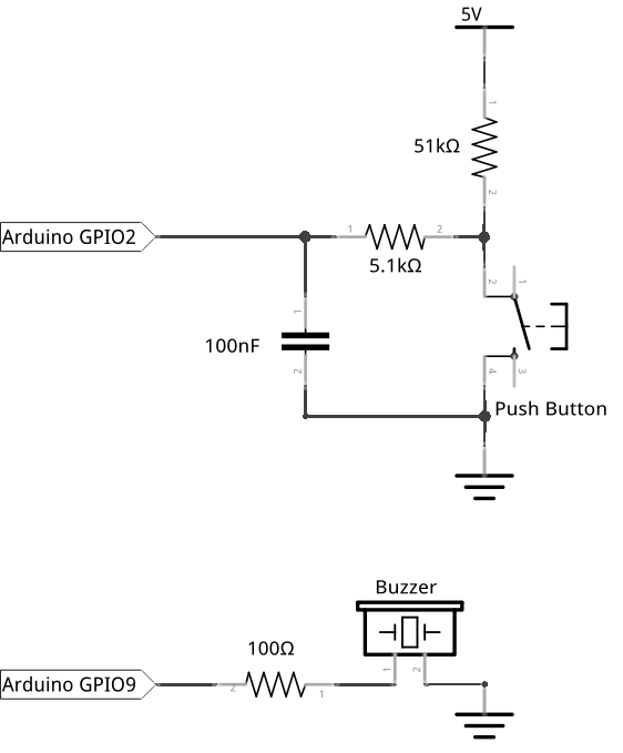
For this experiment, we will be using a push button again for the input and a buzzer for output. Pressing the button will make the buzzer buzz. For the circuit we will need a buzzer, an 100Ω current limiting resistor, and a push button with its debounce circuit setup on a breadboard:
What You’ll Need
Prepare the following components from your kit:
- Omega plugged into Arduino Dock
- USB Micro-B cable for power
- Breadboard
- 6x Jumper wires (M-M)
- Resistors
- 1x 100Ω
- 1x 5.1kΩ
- 1x 51kΩ
- 1x 100nF Capacitor
- 1x Tactile button
- 1x Buzzer
Hooking up the Components
Once you have all the components ready, it’s time to build!
- First, let’s set up the push button with debounce circuit similar to the push button experiment, we’ll connect this to the Arduino Dock in a bit.
- Connect one end of the 51kΩ resistor to one side of the switch. This can be either pin, but make sure you remember which side is which
- Connect the other end of the 51kΩ resistor to an empty row, this will be where we connect our voltage reference.
- Connect the end of the switch that is currently empty to the
GNDrail with a jumper; again, either pin will do. - Plug one end of the 5.1kΩ resistor to the same row where the switch and 51kΩ resistor are connected
- Plug the other end of the 5.1kΩ resistor to an empty row.
- Using the 100nF capacitor, connect the row where the 5.1kΩ resistor terminates to the
GNDrail.
- Now let’s get the buzzer connected - plug the Buzzer across the channel of your breadboard.
- Using a jumper, connect the negative end of the buzzer (the pin WITHOUT a plus sign) to the
GNDrail. Plug in a 100Ω current limiting resistor across the (+) row of the buzzer and an empty row.
- Connect the
GNDrail to aGNDpin on the Arduino Dock. - Connect the point in the debounce circuit between the 5kΩ resistor and the capacitor to pin
2of the Arduino Dock. - Take a jumper and use it to connect the end of 100Ω resistor and pin
9on the Arduino Dock Connect the
Vcc(red) rail to5V
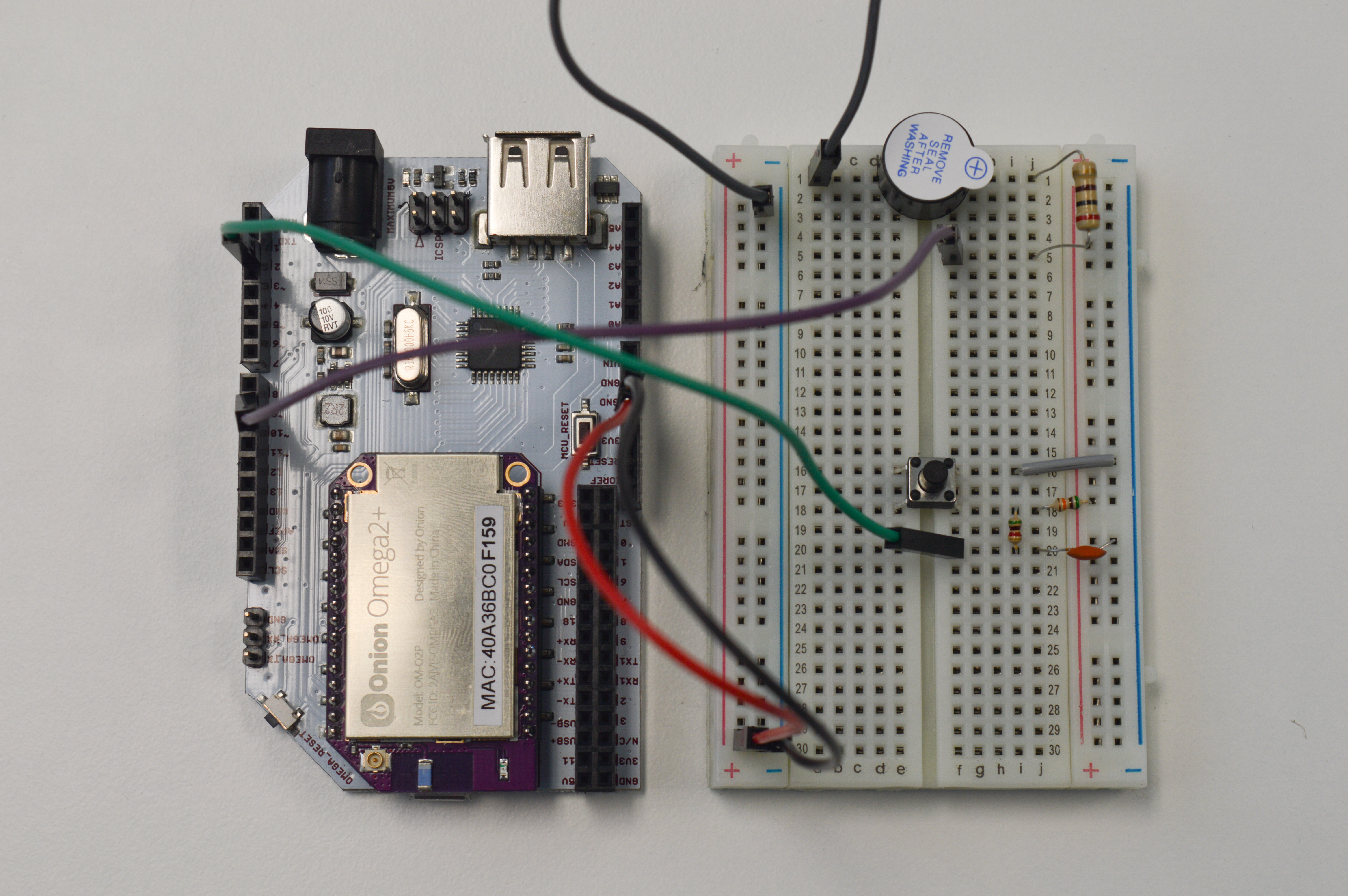
And you’re done! For reference your circuit should look a little like this:
Writing the Polling-based Code
This program will continuously check an input pin to see if anything changes, and then fire the buzzer whenever it does see the appropriate change.
// the pin number connect to the buzzer
int buzzerPin = 9;
// the pin number connected to the push button
int pollingPin = 2;

// This code runs once when the program starts, and no more
void setup() {
   // initialize the buzzer pin as output
   pinMode(buzzerPin, OUTPUT);

   // initialize the polling pin as input
   pinMode(pollingPin, INPUT);
}

// The code in here will run continuously until we turn off the Arduino Dock
void loop() {
    // read the state of the push button
    int state = digitalRead(pollingPin);

    // we want to:
    //   ring the buzzer (buzzer HIGH) when the button is pressed (button LOW)
    //   not buzz (buzzer LOW) when the button is released (button HIGH)
    // note that the buzzer state is opposite of the button state
    digitalWrite(buzzerPin, !state);

    delay(10);
}
What to Expect
When the button is pressed, the buzzer will buzz until the button is released. Pretty simple right?
A Closer Look at the Code
We will approach the simple task of pressing button to make the buzzer buzz in two different ways. The first method, covered here, is constantly polling the push button input. The second method is to get the button to interrupt the program. Check out the experiments on polling and interrupts if you want to go in a bit more detail on either of the methods. For now, let’s start by examining the code above that implements polling.
Polling a Value
In the first method, we poll the input of the push button at a regular interval by setting an ATmega pin as input. Remember from the previous tutorial that the push button input is inverted; therefore, we continuously read the state of the input and continuously write the opposite state !state of the input to the buzzer pin.
| Button | state Variable |
Buzzer | Pin 9 set To |
|---|---|---|---|
| Not Pressed | HIGH | Not Ringing | LOW (!HIGH) |
| Pressed | LOW | Buzzing | HIGH (!LOW) |
Polling has some issues with waste. The idea is to just check the input continuously and perform some actions based on the value of the input. The problem is that, unless the input has changed, all that checking doesn’t do anything useful! To avoid wasting CPU cycles like this, it’s common practice to add a delay to the polling loop.
Of course the downside is that this delay will make your program less responsive. Not only that, if the delay is too long, a short button press might actually be missed! In addition to the fact that we might not successfully capture all inputs, we’re also locked in to just checking the state of that button - our program can’t do anything else!
There must be a better way!
Writing the Interrupt-based Code
An alternative to polling is using interrupt-based inputs. In this approach, we set up code so that when the button changes state, an ‘interrupt’ will be fired off and the appropriate change to the buzzer will be made. This is actually a much better method because there is little to no chance of missing any button presses. Even better, it allows us to do other things because the burden of checking has been lifted. To illustrate the point, we’ll toss in a blinking LED that operates alongside the interrupt code.
Without further ado, here’s the code to do the same thing, but with an interrupt:
// the pin number connected to the buzzer
int buzzerPin = 9;
// the pin number connected to the push button interrupt
int interruptPin = 2;
// the pin number connected to an LED, 13 is the blue LED on board
int LEDPin = 13;
// the state of the buzzer - initially set to LOW (not buzzing)
volatile int state = LOW;

// This code runs once when the program starts, and no more
void setup() {
  // initialize the buzzer pin as output
  pinMode(buzzerPin, OUTPUT);

  // initialize the LED pin as output
  pinMode(LEDPin, OUTPUT);

  // initialize the interrupt pin, calling the changeState function every time there is button press or release
  attachInterrupt(digitalPinToInterrupt(interruptPin), changeState, CHANGE);
}

// The code in here will run continuously until we turn off the Arduino Dock
void loop() {
  // blinking LED regardless of the buzzer
  digitalWrite(LEDPin, HIGH);
  delay(1000);
  digitalWrite(LEDPin, LOW);
  delay(1000);
}

// Interrupt Service Routine (ISR)
//    set the buzzer pin to the appropriate state based on the current push button input value
void changeState() {
  // flip the push button input value since it is inverted due to the debouncing circuit
  state = !state;
  digitalWrite(buzzerPin, state);
}
What to Expect
When the button is pressed, the buzzer will buzz until the button is released. However, this time the blue LED on the Arduino Dock will be able to blink steadily.
A Closer Look at the Code
In this code, we initialize the interrupt by the following line:
attachInterrupt(digitalPinToInterrupt(interruptPin), changeState, CHANGE);This will attach the built-in Arduino interrupt to an interrupt pin (2 or 3). It will call on the Interrupt Service Routine (ISR) function changeState() whenever there is a CHANGE in the push button input. ISR functions cannot have parameters and shouldn’t return anything.
The keyword CHANGE, as described in push button experiment, represents both the FALLING edge (HIGH to LOW) or RISING edge (LOW to HIGH). This means if the input signal changes in any way (the button is pressed OR released), the changeState() ISR function will be called.
The task of the ISR changeState() is to simply write the opposite state of the push button to the buzzer. (Remember, we write the opposite state of the push button because the debouncing circuit inverts the reading of the button). Notice we use the keyword volatile before int when declaring the state variable at the beginning of the program. Although the variable state is global and can be used in the ISR, to make sure the variable is updated correctly between the main program and the ISR, we declare it as volatile.
For the curious,
volatilemeans a variable will be directly modified by something other than the ‘main body’ of the program, and should be loaded from RAM instead of a CPU register - as that is generally where the ‘reference’ value of a variable is stored. Interrupts don’t operate within the main program body, which is why we usedvolatilehere to make sure the value ofstateis properly read.
Since the interrupt and ISR will handle the push button input and setting the buzzer, our program is free to do other things! We’ve added the standard LED blinking code to our loop() similar to the blinking LED experiment. The only difference being we used pin 13 here, which will blink the blue LED on the Arduino Dock.