Controlling Servos
In this tutorial, we will use two push buttons to control two servos: a sub-micro sized servo and a standard sized servo. In addition, we will learn about object oriented programming by creating our own class for servo motors. Nearly all servo motors accept PWM as input, so we’ll be going a bit deeper down that rabbit hole here.
Pulse Width Modulation
Pulse Width Modulation (PWM) is a technique of producing varying analog signals from a digital source.
Digital signals can only be either HIGH or LOW, where the HIGH voltage is some fixed value depending on the circuit. On the Omega, HIGH on the Omega is 3.3V.
On the other hand, an analog signal can be any voltage between HIGH and LOW. Normally, digital circuits can’t freely vary voltage signals, but they can use PWM to get close enough. It works by repeatedly pulsing a HIGH digital signal on and off so that the average voltage coming from the circuit over time would be equivalent to an analog signal between HIGH and LOW. To change the analog voltage, you can vary how fast the HIGH signal is pulsed.
There are some limitations to this method depending on how the driving circuit is built, but it’s relatively simple to implement and can be accurate enough for most cases.
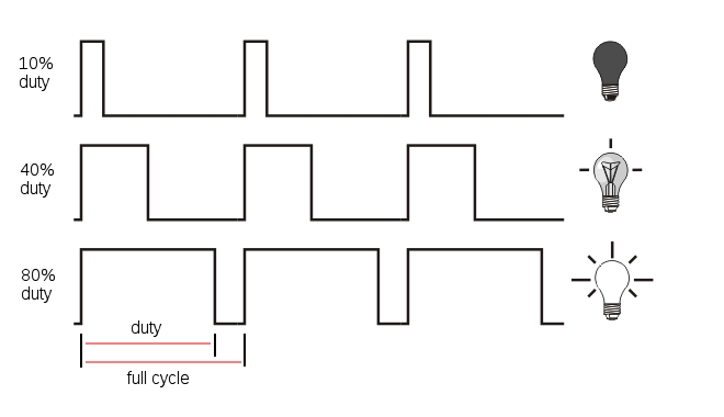
Duty Cycle
In this context, the Duty Cycle indicates what percentage of the time a signal is ON (at logical high - high voltage).
Consider a PWM signal with a 25% duty cycle: it will be on for 25% of the time and off for 75% of the time.
Figuring out the duty cycle is a piece of cake, let’s go over the main components:
- The Time On, Ton, is the amount of time the signal is on (also known as the pulse width)
- The Time Off, Toff, is the amount of time the signal is off
- The total cycle time, Tcycle, is the sum of Ton and Toff
The duty cycle can be calculated as follows:
\[DutyCycle = {\frac{T_{on}}{T_{on}+T_{off}}}\times100\%\]
Period
Indicates the amount of time (usually in milliseconds) for each part of the cycle. The Time On, Ton in the diagram above is the time the signal is high. This is also known as pulse width. Similarly, Time Off, or Toff is the time the signal is low.
The Cycle time corresponds to the overall period of the PWM, or Ton + Toff.
The frequency is the inverse of period:
\[Frequency = {\frac{1}{Period}}\]
For example, a PWM signal with a total cycle time of 20ms has a frequency of 50 Hz. All this means is that the signal will complete 50 full cycles in a second.
How Servos Work
Servo motors are controlled by via a pulse width modulated (PWM) signal. Servo motors usually have three wires: power, ground and the control signal.
Most servos fixedly rotate between 0° and 180° - starting and ending at fixed points relative to the motor. They accept pulses within a fixed range commonly between 500 and 2500us. To put it all together, say we send a 500us width pulse to a servo accepting pulses between 500us and 2500us. The servo will rotate its arm to the 0° position in response - no matter which position the arm was in before. It will respond with appropriate increments when the pulse width is increased up until 2500us, then it will stop moving.
When the servo is receiving signals continuously, it will apply force to attempt to stay in the position that is being signalled. When the servo is unpowered and sent no signals, it won’t actively try to restore position. Manually moving the servo arm is possible when unpowered, but it should not be done as it can damage the servo.
Typical Pulse Width Values
For most servos, providing a 1.5 ms pulse width will place the shaft in the neutral position. Anything greater or less will move the shaft clockwise or counterclockwise. Typical servos can only move 90˚ in either direction from the neutral position. Note that the minimum and maximum shaft positions correspond to minimum and maximum pulse widths, these can vary between servos, so make sure to look at your servo’s datasheet.
The recommended PWM frequency for servos is typically in the range of 40-200 Hz, with most servos using 50 Hz.

Building the Circuit
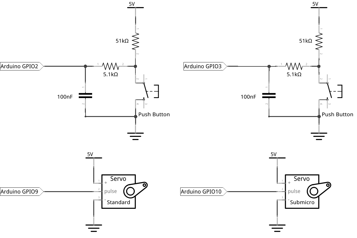
For the circuit, we will need a small (sub-micro size) servo motor (MicroServo DXW90) and a standard size servo motor (Futaba S3003). In addition, we will need two push buttons, each with their own debounce circuits setup on a breadboard. When one button is pressed, both servos will turn to one direction; when the other button is pressed, they both turn to the other direction.
Here’s the circuit diagram for this project:
What You’ll Need
Prepare the following components from your kit:
- Omega plugged into Arduino Dock
- USB Micro-B cable for power
- Breadboard
- Jumper wires
- Resistors
- 2x 5.1kΩ
- 2x 51kΩ
- 2x 100nF Capacitor
- 2x Tactile button
- 1x Servo Motor (Sub-micro size)
- 1x Servo Motor (Standard size)
Hooking Up the Components
Now that you got everything, let’s build!
Let’s first set up the two push buttons with their seperate debounce circuits same as previous tutorials:
1. Set up two push buttons, each with their own debounce circuit similar to tutorial 4, don’t connect to Arduino Dock yet.
1. Instead of connecting 51kΩ resistor to an empty row, we’ll connect them to the Vcc rail.
Now that the buttons are set up, w
e’ll connect the two servo motors:
1. The small servo has 3 wires: connect the brown wire to the GND rail, the red wire to the Vcc rail. We’ll connect the orange (signal) wire in a bit.
* Repeat for the standard sized servo.
Now that our components are set up, we’ll connect them to the Arduino Dock:
1. Connect the negative power rail to a GND pin on the Arduino Dock.
1. Connect the point in the first debounce circuit between the 5.1kΩ resistor and the capacitor to pin 2 of the Arduino Dock.
* Repeat for the second debounce circuit, but plug the jumper into pin 3 instead
1. Connect the orange wire of small servo to pin 9 on the Arduino Dock, and the signal of the standard servo to pin 10.
1. Connect the positive power rail to 5V. Don’t worry if the servo rotates a bit when you power it on - this is expected.
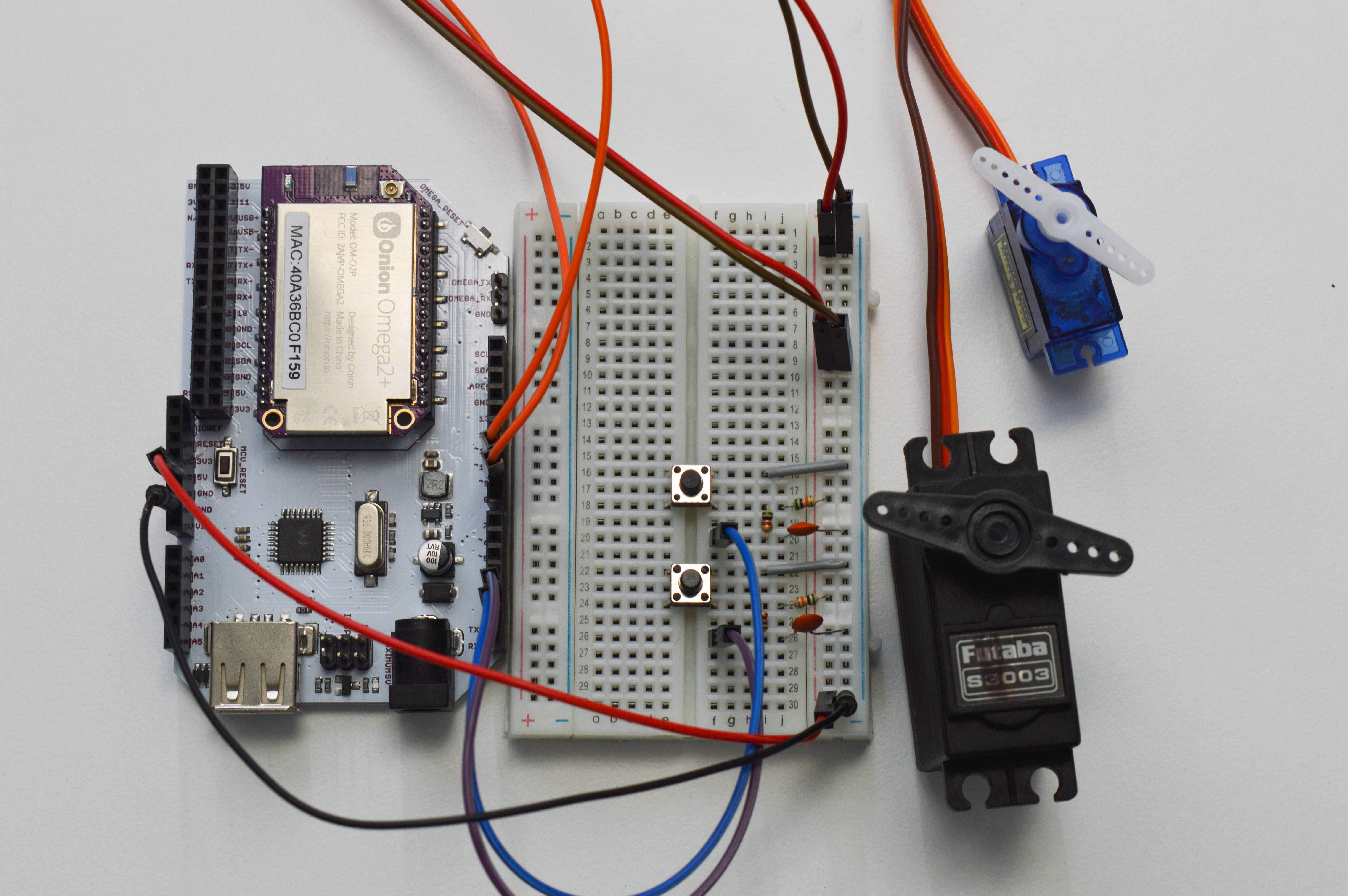
Here’s what the circuit looks like fully assembled:
Writing the Code
Now that the circuit is wired, it’s time to write the code that makes it go!
In order to drive the servo, we’ll create a servo class conforming to the limits of our motors in the sketch by leveraging the functions provided by the Servo.h Arduino Library. This allows us to reuse the code for the future, in addition to making our setup() and loop() functions much more readable.
To get your servos turning, copy the code below into SKA08-usingServo.ino and flash it to your Arduino Dock.
// import the Arduino Servo library
#include <Servo.h>

#define ABSOLUTE_ANGLE_CHANGE   5

// variables to hold program data
int incrementButton = 2;
int decrementButton = 3;
int currentAngle = 90;


// class to control servo motors
class ServoMotor
{
  // variables or functions that can only be used within the ServoMotor class
  private:
  Servo servo;           // Servo object from the Arduino Servo library
  float rate;            // rate of pulse width change per degree
  float minPW, maxPW;    // min and max pulse width in microseconds (uS)
  int minAngle = 0;
  int maxAngle = 180;
  int pin;

  //  variables or functions which can be called outside in the main program
  public:

  // ServoMotor() - constructor for a class with the same name
  // - will be automatically called when a class object is declared
  // - to use, pass in the pin number, max and min pulse width for the motor
    // - the class has functions to use given input to rotate the motor by
    //   arbitrary degrees
  ServoMotor(int pinNumber, float minPWus, float maxPWus){
    // store the pin number, max and min pulse width in private variables
    pin = pinNumber;
    minPW = minPWus;
    maxPW = maxPWus;

    // calculate the pulse width change for each degree
    rate = (maxPWus - minPWus)/(float)(maxAngle - minAngle);


    // attach the specified pin to the Arduino Servo library object
    servo.attach(pin);
  }

  // function where you pass in an angle and it sets the servo motor to that angle
  void setAngle(float angle){

    // if the angle is greater than max angle or less than min angle, print the correct error message and exit the function
    if (angle > maxAngle){
      //Serial.println("Servo angle over maximum. Please press decrease button");
      return;
    }
    if (angle < minAngle){
      Serial.println("Servo angle lower than minimum. Please press increase button");
      return;
      Serial.println("This happens after return");
    }

    // convert the angle to pulse width in microseconds(uS) using the rate previously calculated in the constructor
    float PWus = minPW + rate * angle;

    PWus = (int)PWus;

    // outputs the pulse width sent to the servo library, useful for debugging
    //Serial.println(PWus);


    // set the servo angle by sending the calculated pulse width to the servo motor using the Arduino Servo library
    servo.writeMicroseconds(PWus);
  }
};


// Create two servo objects, one for each motor attached
ServoMotor *smallServo;
ServoMotor *standardServo;

void setup() {    // codes to be run once
  Serial.begin(9600);  // initializing serial communication with the Omega

  // initialize the two servo objects
  smallServo = new ServoMotor (9, 500, 2500);     // initialize small servo (500us to 2500us) at pin 9
  standardServo = new ServoMotor (10, 500, 2500);     // initialize standard servo (0us to 2500us) at pin 10

  // initialize the pins connected to the increment and decrement buttons
  pinMode(incrementButton, INPUT);
  pinMode(decrementButton, INPUT);

  // set the initial angle of the two servos to 90 degrees
  smallServo->setAngle(currentAngle);
  standardServo->setAngle(currentAngle);
}

void loop() {   // code to be run continuously
  // read the state of the two push buttons (1 - not pressed, 0 - pressed) at the pins defined at the start of code
  int increment = digitalRead(incrementButton);
  int decrement = digitalRead(decrementButton);

  int angleChange = 0;

  if (increment == 0) {
    // if the increment button is pressed, increase the current angle
    angleChange = ABSOLUTE_ANGLE_CHANGE;
  }
  else if (decrement == 0) {
    // if the decrement button is pressed, decrease the current angle
    angleChange = -1 * ABSOLUTE_ANGLE_CHANGE;
  }

  // carry out the angle change only if one of the buttons is pressed
  //  having this separate if statement reduces repeated code
  if (increment == 0 || decrement == 0) {
    currentAngle = currentAngle + angleChange;
    Serial.print("Current angle: "); Serial.println (currentAngle);     //print the current angle

    // set both servos to the new angle
    smallServo->setAngle(currentAngle);
    standardServo->setAngle(currentAngle);
  }

  // add a delay so that if either button is held down, the servo angle will change at a maximum rate of 5 degrees every 0.2 seconds
  delay(200);
}
What to Expect
When one button is pressed, both servos will turn to one direction; when the other button is pressed, they both turn to the other direction. If either button is pressed and held down, the servos’ shaft position will either increase or decrease by 5° every 0.2 seconds.
Heres what it looks like:
A Closer Look at the Code
In this code, we introduce a very important, new concept: Object Oriented Programming (OOP). We will take a look at some of the key elements of OOP: classes, objects, constructors and class members.
Object Oriented Programming
In our experiment, we have two servos, they operate in the same way but some attributes (parameters) are slightly different: attached pin number, minimum pulse width, maximum pulse width. This is exactly the kind of scenario that spurred the creation of Object Oriented Programming. Ultimately, the goal of OOP is to model programmatic interactions as objects interacting with each other.
To that end, we create objects that represent this model. In this experiment, our objects are the two servos we use.
Objects don’t normally appear out of thin air - the computer needs to know how they will work before they can be created. To that end, objects are created as instances of templates known as classes. A class will define what attributes its objects will have, and the functions that interact with the attributes.
Classes
So if classes are templates, how do we use them?
There’s two steps. First we need to create the class itself. Once the class is created, then we can create objects from the class - more specifically, instances of the class.
Let’s take it back to our code above. First thing you’ll notice relating to our class is probably:
This is our class definition! All the code inside defines what an instance of ServoMotor would encompass. It’s got attributes, methods, public’s, and private’s. One interesting thing about the class is that, by default, no attribute inside a class actually exist in memory. Attributes of a class become actual data when we make an object out of it - commonly known as instantiating a class.
Most object oriented languages allow functions inside classes to be executed without an instance under certain conditions.
Generally in a language that supports OOP, classes must be declared and loaded into a program before instances of that class can be created.
Objects
Where in our code do we create objects? Right here:
  smallServo = new ServoMotor (9, 500, 2500);     // initialize small servo (500us to 2500us) at pin 9
  standardServo = new ServoMotor (10, 500, 2500);     // initialize standard servo (0us to 2500us) at pin 10
The syntax to instantiate a class is very similar to creating variables of a certain type. In fact that’s one way to think about classes and objects - types and variables with fancier internals.
Unlike variables, we work with objects by calling the methods (functions) defined by the class. The variables inside objects are not normally manipulated from ‘outside’ the object.
Let’s look back to the objects and classes to variables and types analogy. If objects are like variables of a class, then why do we have brackets and pass in arguments like a function?
This is because the attributes of an object are fancier than ints or chars - objects can have other objects as variables. So in order to provide the flexibility needed, a function is called to instantiate a class by setting up all the things needed for it to work as expected. The syntax in the snippet above is actually short-hand for a two-step process:
- Call a function to instantiate the class and set up the internals of the instance, returning a reference to the created object.
- Assign the returned object to a variable (
smallServoandstandardServoabove)
So if you want an object, which function are you going to call?
Constructors
Let’s take a look at this snippet:
    ServoMotor(int pinNumber, float minPWus, float maxPWus){

        // pass in the pin number, max and min pulse width to private variables
        minPW = minPWus;
        maxPW = maxPWus;
        pin = pinNumber;

        // calculate the pulse width change for each degree
        rate = (maxPWus - minPWus)/(maxAngle - minAngle);
    }
This is the constructor of ServoMotor class. Whenever the code demands that a new ServoMotor object be created, this is the function that is called.
More formally, a constructor is function of the class that has the exact same name as the class and will be automatically called when a class object is created.
In the snippet where we declared a new ServoMotor object (replicated just below), there’s this new keyword. In many object oriented programming languages, this is the keyword that differentiates calling a class constructor (that brings back an object) versus naming the class itself - which may have functions that are useable without an object.
Class Members
You’ll occasionally hear people refer to ‘members’ of a class. A class member is a variable or a function declared as a part of the class template.
In most object oriented languages, class members have access rights - either private or public. A private member can only be used within the class. While a public member can be called outside the class. For our ServoMotor class, we have seven private members (six variables and one object) declared under private: and two public member functions defined under public:. Our public member functions include the constructor ServoMotor() and another function setAngle().
Putting it Together
To use our ServoClass template, we declared our two objects in the global scope similar to declaring global variables:
When the lines above are run, the objects haven’t been constructed yet, what we’ve done instead is create pointers of the type ServoMotor.
To actually make some serviceable objects, we call the new keyword in our setup() function as mentioned above and then put their addresses as the values of the pointers we’ve created above with the = operator.
A pointer is a variable that is exactly the size of a memory address on the system it’s created in. It’s a highly useful construct in C/C++ and arduino code as it enables arrays, objects and other kinds of complex data structures.
Note that ServoMotor instances can only be defined after our ServoMotor class has been defined. That’s why we declare the object pointers after the class definition.
Once we have the two objects instantiated, we can call setAngle() on either of the two objects in our main program:
You’ll notices from the code that the setAngle() member function is declared under the public: line. This tells the computer that it is exposed to any code that creates an object. The -> notation is to denote the smallServo variable as a pointer to an object, not a direct object of the ServoMotor class.
Furthermore, notice we have seven private member variables but we only passed in three parameters (pinNumer, minPWus, maxPWus). They are assigned to three private member variable (pin, minPW, maxPW) in our constructor. This is because the three parameters are the only different parameters between different servo objects. The other variables are all either common between instances or calculated from these three initial values.
For example, the rate variable is calculated from the scaled difference between minPWus and maxPWus parameters. The minimum and maximum servo angle (minAngle and maxAngle) are set to 0 degree and 180 degree for all ServoMotor objects.
Lastly, we use a Servo object from the Arduino Servo library within our own ServoMotor class to interface with our Arduino Dock pins directly, so we don’t have to directly handle the PWM driver of the Arduino Dock!
Pointers
We’ve touched on pointers a little bit above, but in fact they are incredibly important to C/C++. It’s a very deep topic that’s not super relevant to this experiment, but it’s very helpful to have some working knowledge about them when creating Arduino projects.