Controlling Many LEDs
“Alright, we’ve blinked one LED, should we try a second?”
In this experiment, we’re going to use what we learned in the first experiment and wire up a bunch of LEDs. Then we’re going to get them to blink in a cool pattern with code!
Building the Circuit
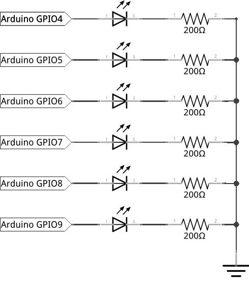
Similar to the previously experiment, we need our breadboard and jumper wires. However, now we will use six LEDs along with six current limiting resistors. We will makes the LEDs turn on one-by-one going left to right, and then turn them off one-by-one again going left to right.
Here’s the diagram of our circuit for reference:
What You’ll Need
Prepare the following components from your kit:
- Omega plugged into Arduino Dock
- USB Micro-B cable for power
- Breadboard
- 7x Jumper wires (M-M)
- 6x 200Ω Resistors
- 6x LED color of your choice!
Hooking up the Components
While the individual LEDs will be connected in exactly the same way as in the first experiment, we’re going to be using the rails on the breadboard to make the wiring a little simpler. Here rails aren’t of the train variety - they’re the four vertically connected columns on each side of the breadboard. You’ll see in a second why they’re super handy.
To get started, let’s grab six LEDs and let’s do the following for each one:
- Plug in the LED into the breadboard across the center channel - make sure to keep the anodes and cathodes for each LED on the same sides!
- Connect one end of a 200Ω resistor to the cathode row, and the other end into the column marked
-- This column will see a ton of use in complicated projects, now and in the future, we’ll call it the
GNDrail.
- This column will see a ton of use in complicated projects, now and in the future, we’ll call it the
You can probably guess that the column labelled
+will be used to share a power supply. We’ll be calling it theVccrail often in the future!
Once you’ve done the above for all six LEDs, let’s connect a jumper wire from the GND rail on the breadboard to a Ground pin on the Omega - those will be labelled GND. Since the two red and blue rails are connected vertically, what we’ve done is connect all of the LED cathodes to the Ground using just one pin on the Arduino Dock.
To finish off the circuit, we need to connect the anodes of our LEDs to GPIOs on the Arduino Dock. We’ll be using six digital GPIOs (9, 8, 7, 6, 5, 4) on the Arduino Dock (near the jack barrel connector).
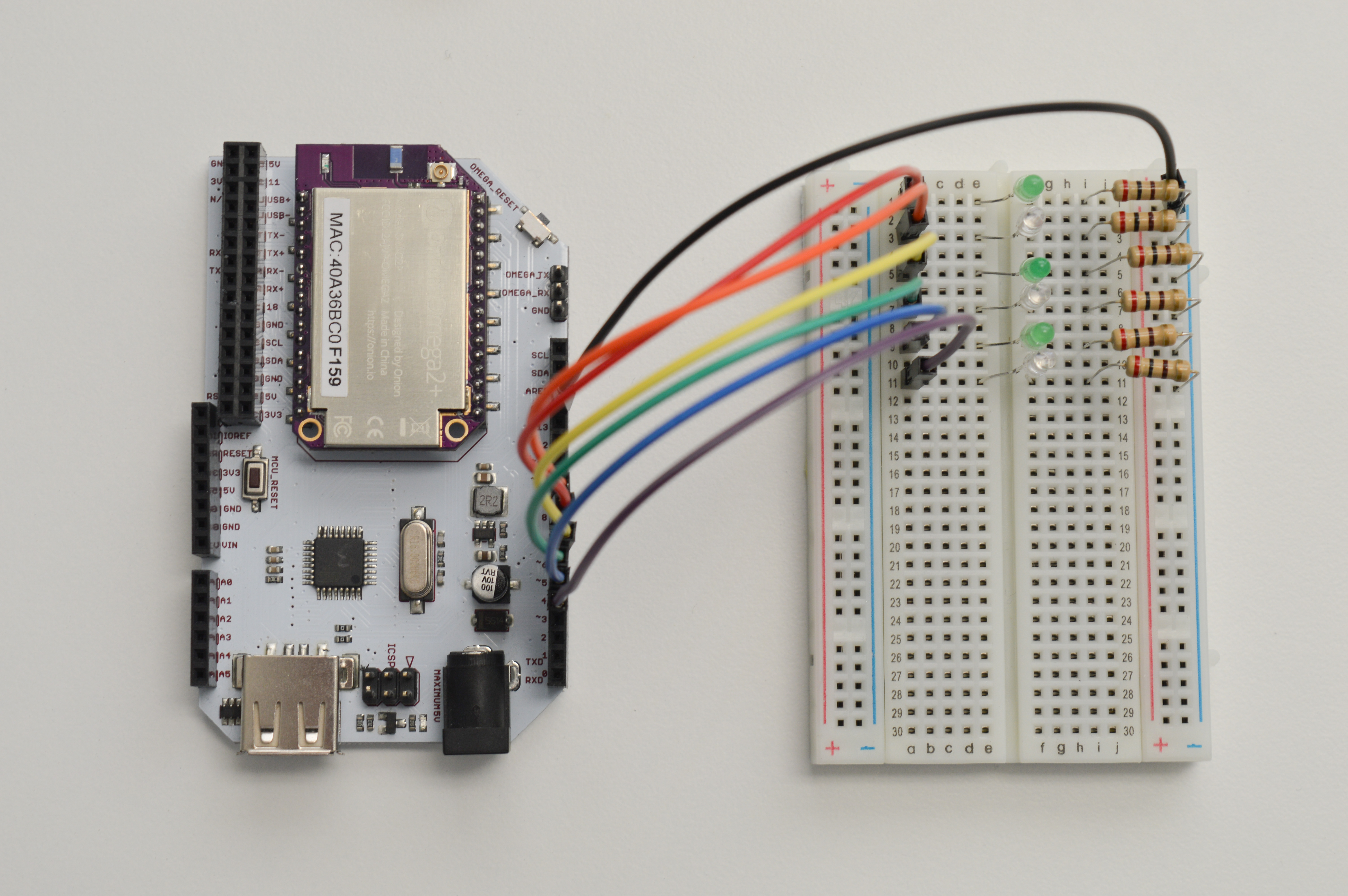
Once your done, the circuit should look something like this:
Writing the Code
Now let’s operate the LEDs with some programming. We’ll write an Arduino sketch that turns the LEDs on one-by-one, then turns them off in the same order.
Let’s save the code below as SKA02-multipleLeds.ino:
// time delay between each LED in ms
int timer = 100;
// an array of GPIO pin numbers where LEDs are attached
int ledPins[] = {9, 8, 7, 6, 5, 4};

int pinCount = sizeof(ledPins)/sizeof(int);
// Above, sizeof() checks for the size of the input and returns it as the number
// of bytes the input takes up.
// ledPins is an array of integers, so we divide the result by the sizeof(int)
// to get the number of pins we have automatically.

void setup() {
  // loop that initializes the GPIOs
  for (int thisPin = 0; thisPin < pinCount; thisPin++) {
    pinMode(ledPins[thisPin], OUTPUT);
  }
}

void loop() {
  // This loop turns on the GPIOs one-by-one going left to right
  for (int thisPin = 0; thisPin < pinCount; thisPin++) {
    digitalWrite(ledPins[thisPin], HIGH);
    delay(timer);
  }

  // This loop turns the GPIOs off instead - in the same order
  for (int thisPin = 0; thisPin < pinCount; thisPin++) {
    digitalWrite(ledPins[thisPin], LOW);
    delay(timer);
  }
}
What to Expect
Your line-up of LEDs will be essentially chasing it’s tail: the left-most LED will turn on, and then the next one, and the next and so on. When all of them turn on, the left-most one will turn off, and the rest will follow suit.
Here’s what it looks like:
A Closer Look at the Code
In this code, we get getto see the difference adding more LEDs make. Turns out not too much! We use a couple of new concepts to do more things with very similar code - we declared the pins as an array, and used for-loops to do the same thing over and over again. Let’s take a look.
Arrays
In the second line of our code, we defined the ledPins[] variable. It looks a little different from the variables we’ve encountered up to now. The pair of square brackets ([]) here tells the computer to make ledPins an array.
So far, we’ve interacted with int variables - representing an integer number in memory. Later, we’ll deal with char variables to represent characters. But an array isn’t really the same as those two. An array is a list of variables, with the ability to access each individual variable - they can be of any type. A single variable in an array is referred to as an element.
The ledPins array is meant to hold the GPIO pin numbers that control our LEDs. So the ledPins array will hold a bunch of integers as declared first thing in that line. In addition to that, we’re populating the array as soon as we declare it by assigning it a value of {9, 8, 7, 6, 5, 4} with the equals sign.
An important thing to remember is that the the first element is element 0 and second element is element 1, and so on. The last element is numbered one less than the length of the array. This is almost universally the case in programming, so you’ll get used to it if you keep coding!
The square brackets [] mean slightly different things when declaring the array versus when actually using the array. When declaring the array, it acts as a signal saing ‘this variable is an array’. When using the array, we use the square brackets to specify which element of the array we wil be using. For example, ledPin[0] will call the first element of the array, which is 9.
When declaring an array in Arduino (which uses C), it’s very good practice to choose one of the three options below:
* Declare the size of the array - int ledPins[6]
* Or assign it a value - int ledPins[] = {9, 8, ..., 4}
* Both at the same time
We won’t cover what happens when you don’t, as that’s a very large tangent. If you want to know more about why, look up ‘dynamic memory allocation’ and ‘malloc()’.
For Loop
As a bit of background, loops are programming constructs that repeatedly run a block code until some condition is no longer met. Loops are incredibly common in literally every type and form of programming. We already saw an example of it in the previous tutorial where we talked about the loop() function. Naturally, we can create our own loops with custom conditions.
For our program, we need to perform 3 actions on each pin. First, we set the mode to output, then we turn it on, and finally we turn it off. Let’s say we want to turn all the pins off: without looping, we’ll have to write digitalWrite(ledPins[0], HIGH); once for each LED we’re running, that’s six times for this circuit!
Instead of doing that, we can use what we know about the LED array to make a loop. Enter, the for-loop:
This is what the header of a for-loop looks like
for (int thisPin = 0; thisPin < pinCount; thisPin++) {The for in the beginning is a keyword, it signifies the beginning of a loop. The brackets () enclose the setup of the loop. In the case of the for-loop, there’s three parts to the setup separated by semi-colons.
The first part (int thisPin = 0;) declares a counter variable storing the number of iteraitons so far. We initialize it as 0 because our array begins at 0 (you might see where this is going already).
The second part (thisPin < pinCount) is the condition statement. Note that it isn’t a stopping condition! It is a continue condition, meaning the loop stops if and only if the condition becomes false (or evaluates to 0). For our case, we want to run the loop until the counter is at the last element of the array. This is why the condition compares the current iteration number with the total number of pins we have. We declared a variable called pinCount at the start so we have it handy for exactly this purpose.
The third part (thisPin++) is code that runs after each iteration. In our code, we want to increment our counter by one every cycle so we go through all the elements of the array one-by-one
For each pin, we need to do three things. So reasonably, we use three loops: one for setting all pins as output pins, one for turn on all the LEDs, and one to turn off all the LEDs. We put these loops in sequence so they run one after the other. In setup() all the pins are set to output with one loop. In loop() the two for loops run one after the other, turning all the LEDs on, and then all of them off.
Gotta go Fast
If you’re wondering why we make the program sleep for a second during each loop iteration, it’s because computers execute program code really fast. Try increasing, decreasing, or getting rid of the sleep instruction altogether and rerunning the program. See what happens with our LEDs.