Controlling a 7-Segment Display
For this tutorial, we will learn how to use a seven-segment display. In addition, we will learn how to send data from the Omega to the ATmega through the serial connection. This way we don’t have to reflash the ATmega everytime we want to display something new on the display.
7-Segment Display
If you’re wondering why it’s called a 7-segment display, wonder no more!
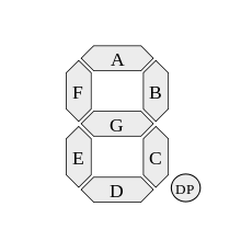
If you take a look at a 7-segment display closely you’ll see that each digit is split into seven different segments, each lit up by an LED. Each segment is connected directly to an input pin and is controlled individually. See the diagram below for a typical labelling scheme:
7-segment displays with more than one digit usually have each segment connected in parallel across all of the digits; this is to save pins on the display module itself. For example, if you try to light up the segments will display a “1”, it will appear on all of the digits at the same time!
This isn’t really useful, so each digit has its own scan pin that groups segments for each digit together. This pin then controls whether the digit’s LEDs can be turned on or not.
To control the segments on a single-digit 7-seg display, you need at least seven GPIOs. And in order to control multiple digits at once, we need one additional GPIO for each scan pin. This can really add up, so we can use a shift register to increase the number of output pins available to us. This is usually how 7-segs are incorporated into a project in order to minimize the number of pins used on the controller.
7-segment displays are sometimes called “7-segs” for short.
Building the Circuit
For this experiment, we will send a string from the Omega to the ATmega through the serial port. To prove we’ve done it, we’ll display the first four characters on the seven segment display. Since we have a wealth of pins available on the microcontroller, we’ll opt out of using a shift register for this experiment.
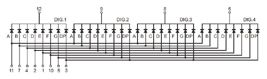
We will need the four-digit seven-segment display and eight 1kΩ current limiting resistors for each of the eight scan (digit select) pins. The 12 pins of the seven-segment display can be grouped into two types: segment pins and digit select (scan) pins. The current limiting resistors are to protect the LED in each of the segments. There are four digits and there are eight segments for each digit (including the decimal point). Therefore, there are a total of 4 x 8 = 32 LEDs.
What You’ll Need
Prepare the following components from your kit:
- Omega plugged into Arduino Dock
- USB Micro-B cable for power
- Breadboard
- Jumper wires
- 12x Male-to-Female
- 6x Male-to-Male
- 8x 1kΩ Resistors
- 1x Seven Segment display
Hooking up the Components
The seven segment display from the kit has some properties that can be used to properly wire it. First, the cathode of LEDs are connected to the digit pins. Second, their anodes are connected to the scan pins. This means we can selectively place current limiting resistors on only the pins that need it. We’ll also have to consider how many LEDs are connected to each pin calculate resistance accordingly - but not to worry, that’s already been done.
The seven segment display is not labelled, so we’ll have to reference the pinout diagram to make sure the correct connections are being made. When facing the front of seven segment display with decimal points at the bottom, the bottom row of pins are numbered 1 to 6 going from left to right and the top row of pins are numbered 7 to 12 going from right to left.
We will need to connect all 12 pins of the seven segment display to 12 digital pins of the Arduino Dock.
Here’s the circuit diagram for reference.
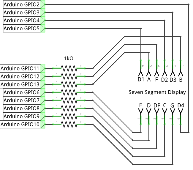
- Connect the digit pins (
6,8,9,12) of the seven seg to the GPIO pins2,3,4,5on the Arduino Dock respectively. - Cconnect the scan pins (
1,2,3,4,5,7,10,11) of the seven seg each to a different 1K resistor then to the pins6,7,8,9,10,11,12,13on the Arduino Dock respectively.
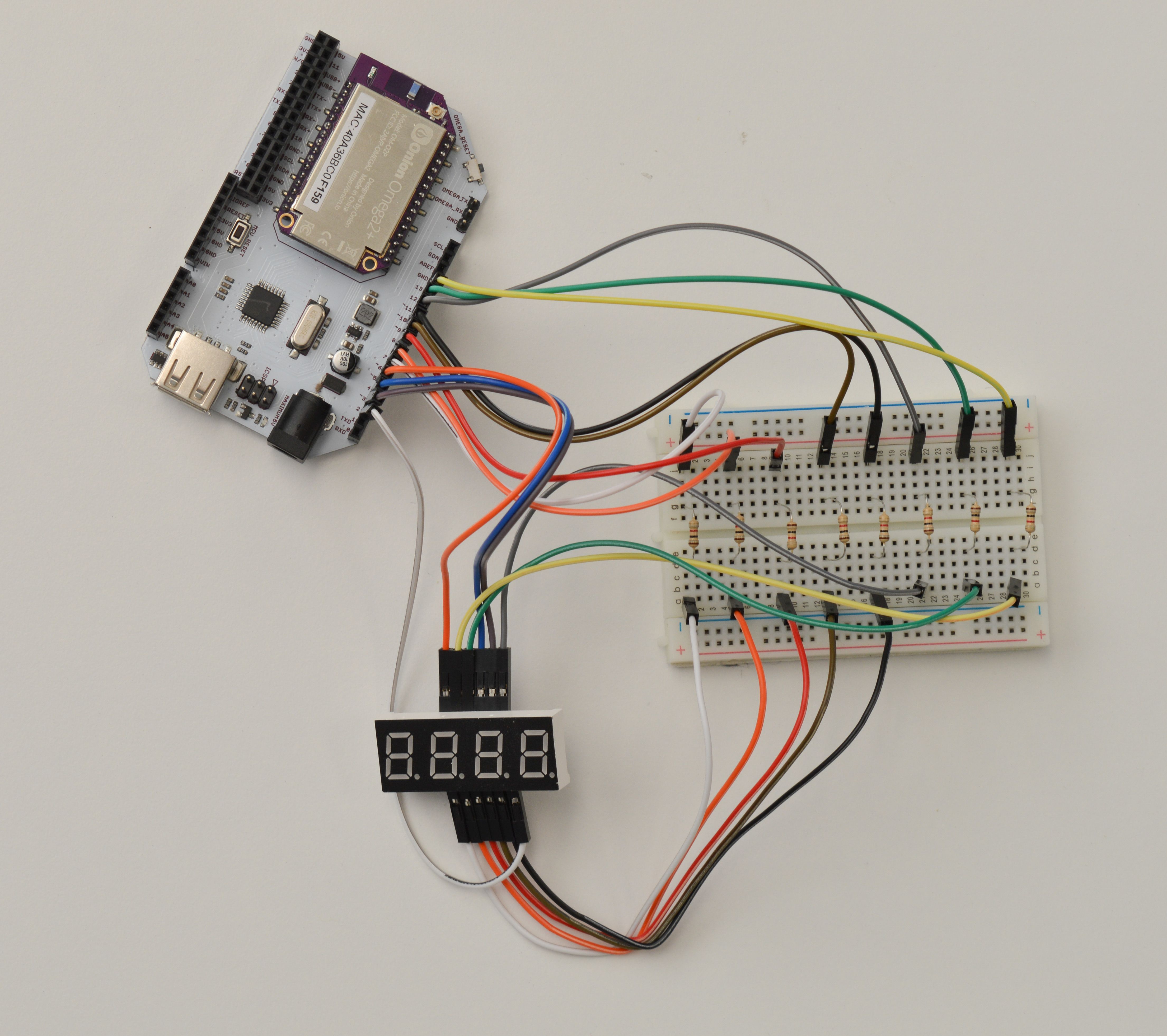
- For this step, we’ll connect the pins to the resistors through the breadboard for ease of service.
- For each connection, plug the resistor across the center channel of the breadboard, and connect the relevant pins one to each end - scan pin
1to Arduino GPIO6, and so on.
Once done, it should look something like this:
Writing the Code
The code will do two things: 1. Read incoming data from the serial connection to the Omega. 1. Error check, translate, and display the data on the seven segment display.
#define NUM_7SEG_DIGITS       4
#define NUM_7SEG_SEGMENTS     8
#define NUM_INPUT_CHARS       9

// array of bytes, each byte represents how different characters will be displayed on the 7-seg
static const byte digitCodeMap[] = {
 //DpGFEDCBA  Element  Char   7-segment map:
  B00111111, // 0   "0"          AAA
  B00000110, // 1   "1"         F   B
  B01011011, // 2   "2"         F   B
  B01001111, // 3   "3"          GGG
  B01100110, // 4   "4"         E   C
  B01101101, // 5   "5"         E   C
  B01111101, // 6   "6"          DDD
  B00000111, // 7   "7"
  B01111111, // 8   "8"
  B01101111, // 9   "9"
  B01110111, // 10  'A'
  B01111100, // 11  'b'
  B00111001, // 12  'C'
  B01011110, // 13  'd'
  B01111001, // 14  'E'
  B01110001, // 15  'F'
  B00111101, // 16  'G'
  B01110110, // 17  'H'
  B00000110, // 18  'I'
  B00001110, // 19  'J'
  B01110110, // 20  'K'  Same as 'H'
  B00111000, // 21  'L'
  B00000000, // 22  'M'  NO DISPLAY
  B01010100, // 23  'n'
  B00111111, // 24  'O'
  B01110011, // 25  'P'
  B01100111, // 26  'q'
  B01010000, // 27  'r'
  B01101101, // 28  'S'
  B01111000, // 29  't'
  B00111110, // 30  'U'
  B00111110, // 31  'V'  Same as 'U'
  B00000000, // 32  'W'  NO DISPLAY
  B01110110, // 33  'X'  Same as 'H'
  B01101110, // 34  'y'
  B01011011, // 35  'Z'  Same as '2'
  B00000000, // 36  ' '  BLANK
  B01000000, // 37  '-'  DASH
};

// number of digits
//  array of pins to control the digits: 1,2,3,4
byte digitPins[] = {5, 4, 3, 2};
// array of pins to control the segments: A,B,C,D,E,F,G,Period
byte segmentPins[] = {13, 11, 9, 7, 6, 12, 10, 8};

// array of 4 bytes to be displayed, each byte representing a digit
//     initially set to represent '1234'
byte currentCharacters[NUM_7SEG_DIGITS] = {digitCodeMap[1],digitCodeMap[2],digitCodeMap[3],digitCodeMap[4]};

// declare functions that will be used in the loop() function
void     displayDigits();
void     stringToDigits(String inputString);


// This code runs once when the program starts, and no more
void setup()
{
    // initialize serial communication with the Omega
    Serial.begin(9600);

    // loop for setting all the digit select (scan) pins to output and then off (HIGH)
    for (byte digitIndex = 0 ; digitIndex < NUM_7SEG_DIGITS ; digitIndex++) {
        pinMode(digitPins[digitIndex], OUTPUT);
        digitalWrite(digitPins[digitIndex], HIGH);
    }

    // loop for setting all the segment pins to output and then off (LOW)
    for (byte segmentIndex = 0 ; segmentIndex < NUM_7SEG_SEGMENTS ; segmentIndex++) {
        pinMode(segmentPins[segmentIndex], OUTPUT);
        digitalWrite(segmentPins[segmentIndex], LOW);
    }
}

// The code in here will run continuously until we turn off the Arduino Dock
void loop()
{
    // display the digits stored in the currentCharacters array
    displayDigits();

    // check for serial data coming from the Omega
    if (Serial.available() > 0){
        // read the incoming data as a string
        String serialString = Serial.readString();
        Serial.println(serialString);

        // convert the string into bytes that can be displayed on the 7seg (and store them in the currentCharacters array)
        stringToDigits(serialString);
    }
}


//// function definitions
// write the digits currently stored in the currentCharacters to the 7-segment display
void displayDigits()
{
    //// nested for loop for displaying all the digits and their segments based on currentCharacters[], which is an array of 4 bytes
    // for each digit, set the specific digit pin LOW, turn on the correct segments, set the digit pin HIGH again
    for (byte digitIndex = 0 ; digitIndex < NUM_7SEG_DIGITS ; digitIndex++) {
        // pull the current digit pin LOW to enable displaying the segments
        digitalWrite(digitPins[digitIndex], LOW);

        // a variable to hold the encoding of the current character
        byte currentCharacter = currentCharacters[digitIndex];

        // set the correct segments on for current digit based on the current character encoding
        for (byte segmentIndex = 0 ; segmentIndex < NUM_7SEG_SEGMENTS ; segmentIndex++) {
            // to the pin associated with the current segment,
            // write the bit from the currentCharacter that corresponds to the current segment
            byte ledValue = (currentCharacter >> segmentIndex) & 0x01;
            digitalWrite(segmentPins[segmentIndex], ledValue);
        }

        // delay before disabling the current digit so the human eye can observe it
        delay(5);
        // pull the current digit pin HIGH to disable display of the segments
        digitalWrite(digitPins[digitIndex], HIGH);
    }
}

// convert an input string into bytes can be displayed on the 7seg,
//    store them in the currentCharacters array
void stringToDigits(String inputString)
{
    byte     digitIndex = 0; // keep track of which digit on the display we're currently setting up
    char     inputCharacters[NUM_INPUT_CHARS];

    // convert the incoming data into a char array
    inputString.toCharArray(inputCharacters, NUM_INPUT_CHARS);

    // attempt to match each character from the input to bytes that can be displayed on the 7-seg
    for (byte index = 0 ; index < NUM_INPUT_CHARS ; index++) {
        // convert a character to a integer (based on the ASCII table)
        int charToInt = inputCharacters[index];
        Serial.println(charToInt);

        // case statement for matching the integer value of each character the an element from the digitCodeMap[] array
        switch (charToInt) {
            case 48 ... 57:   //0-9
                currentCharacters[digitIndex] = digitCodeMap[charToInt-'0'];    // subtract the integer ASCII value for '0' to be able to correctly index our digitCodeMap array
                break;

            case 65 ... 90: // A-Z
                currentCharacters[digitIndex] = digitCodeMap[charToInt-'A'+10]; // subtract the integer ASCII value for 'A' and add 10 to correctly map the A-Z ASCII values to our digitCodeMap array
                break;

            case 97 ... 122: // a-z
                currentCharacters[digitIndex] = digitCodeMap[charToInt-'a'+10];    // subtract the integer ASCII value for 'a' and 10 to correctly map the a-z ASCII values to our digitCodeMap array
                break;

            case 45:  // dash
                currentCharacters[digitIndex] = digitCodeMap[37];
                break;

            case 32:  // space
                currentCharacters[digitIndex] = digitCodeMap[36];
                break;

            case 46: // dot
                // set the decimal segment for the previous digit
                //    but only if we've already setup a previous digit (to prevent unforeseen errors)
                if (digitIndex > 0) {
                    currentCharacters[digitIndex-1] = currentCharacters[digitIndex-1] | B10000000;
                }
                break;

            default: // not mapped by digitCodeMap, set to blank
                currentCharacters[digitIndex] = digitCodeMap[36];
                break;
        }

        // increment the digit index to the next index
        //    but only if the character we just looked at was not a dot
        //    since dots get added to the previous digit
        if (charToInt != 46) {
            digitIndex++;
        }

        // prematurely end the loop if we've decoded enough digits to fill the entire display
        if (digitIndex > NUM_7SEG_DIGITS) {
            break;
        }
    }
}
What to Expect
When the code has being flashed on the ATmega, the seven segment display should display the characters 1234. If we use the following command on our Omega:
echo -ne 'AAAA' > /dev/ttyS1Just like this:
We should see the characters inside the single quoation mark ’’ displayed on our seven segment display. By default echo will send the data and start a new line (‘/n’) after the data; we use the -ne operator to remove the new line. We can send any number and alphabet except for ‘M’ and ‘W’. There will only be one way to display an alphabet regardless of its case. We can also send space ’ ’ and dash ‘-’; any characters that cannot be displayed will be replaced with a blank space ’ ’.
In addition, we can also add decimal points in the string we send from the Omega. If the first character sent is a decimal point, it will not be displayed.
A Closer Look at the Code
There’s lots going on in this code, but the main operations are to receive character data through the serial port, translate the characters to data that can be displayed on the 7-segment display, and then actively display all of those characters on the display.
The topics that we’re going to take a closer look at include:
- A description of the overall flow of the program
- How characters are encoded to be displayed with 7 segments
- How we actually show the characters on the display and what’s really happening vs what it looks like is happening. This part will cover bitwise operations.
- Capturing and converting serial input
- A distinction between declaring and defining functions
Program Flow
In the setup() function, we do the following:
- Initialize serial communication with the Omega
- Initialize all of the pins controlling the digit select (scan) pins on the 7-segment display as Output pins
- Set all of them to HIGH to disable all of the digit selects. Since all of the segment LED anodes are connected to the digit select pins, setting them to HIGH will stop any and all current from flowing through the LEDs. A digit select pin needs to be set to LOW (and a segment pin set to HIGH) in order for current to flow through and illuminate the LED
- Initialize all of the pins controlling the segment pins on the 7-segment display as Output
- Set all of them to LOW to disable all of the segment LEDs
The loop() function will run the displayDigits() function that will display the characters held in the global currentCharacters array. We initialize the currentCharacters array to hold the 7-segment mapping for 1234, so on the very first time the loop() function runs, it will display 1234 on the 7-segment display.
Afterwards, if there is any serial data available to be read, that is, if we’ve sent any data over from the Omega, the serial data will be received, parsed, and the currentCharacters array will be updated to hold 7-segment mapping of the data. On the next time the loop() executes, the displayDigits() function will write the new data from the currentCharacters array to the display, thus displaying the data we sent over from the Omega.
However, if there was no serial data received, the loop() function will complete and execute again, running the displayDigits() function with the same data as before. In a moment, you’ll see why we constantly need to run the displayDigits() function.
Character Encoding
We start the program off by creating a rather large array of bytes, digitCodeMap, that defines each character we can represent on the 7-segment display. The contents of each element define which of the segments need to be enabled in order to properly display the character. Our display defines the segments as follows:
And we define each bit in the byte to correspond to a distinct segment:
| Bit | Corresponding Segment |
|---|---|
| 0 | A |
| 1 | B |
| 2 | C |
| 3 | D |
| 4 | E |
| 5 | F |
| 6 | G |
| 7 | DP - Decimal Point |
So if we look at the 0 character, the binary representation is B00111111, which means segments A, B, C, D, E, and F are enabled. And taking a look at the 1 character, the binary representation of B00000110 translates into only segments B and C being enabled. Try going through some of the other characters yourself and decoding which segments are enabled.
You might have noticed that we defined the digitCodeMap array with the static const keyword prefixes. The const keyword identifies this variable as read-only, meaning the value cannot by changed by the program. The static keyword means that memory for this variable will be allocated at compile-time as opposed to when the program runs. It also means that this variable will be available for the entire run-time of the program. So, defining digitCodeMap as a static const array means that we’ll always be able to quickly access the array (since it’s in the program code and not in memory) and that it will never be changed by the program (since that would mess up how we display our characters).
Displaying the Characters
Now let’s take a look at how we actually draw characters on the 7-segment display with the displayDigits() function. From a high level, we display each of the character encodings stored in the currentCharacters on different digits on the physical display. There’s two parts to this:
- Displaying each digit
- Displaying all of the segments for each digit
Displaying Each Digit
We use nested for loops and perform the same operations for each digit:
- Set the current digit pin to LOW
- Now if any segment pin is set to HIGH, the segment LED will light up
- Loop through all of the bits of the element of the
currentCharactersarray we’re writing now, set the corresponding segment LED pin to HIGH or LOW based on the value of the bit (more on this below) - Small delay to ensure that our digit is visible by the human eye
- Set the current digit pin to HIGH, disabling all segment LEDs for this digit
This works out since we’ve ensured that the pins stored in the digitPins array and the characters stored in the currentCharacters array, correspond to the 7-segment digits in order:
| 7-segment Digit | digitIndex Value |
digitPins Element Value |
currentCharacters Element |
|---|---|---|---|
| Digit 1 | 0 | 5 | Character 1 Encoding |
| Digit 2 | 1 | 4 | Character 2 Encoding |
| Digit 3 | 2 | 3 | Character 3 Encoding |
| Digit 4 | 3 | 2 | Character 4 Encoding |
As we iterate digitIndex, the character encoded in currentCharacters[digitIndex] will get written to the digit that corresponds to the pin in digitPins[digitIndex]. The two arrays are ordered such that we write to Digit 1 first, then Digit 2, Digit 3, and finally, Digit 4.
So as an example, when digitIndex is 2, element currentCharacters[2] will correspond to the encoding for the 3rd character to be displayed, and digitPins[3] (which is 3) is the pin that’s connected to the digit select for the 3rd digit on the 7-segment display.
Displaying the Segments
Similar to the above, we’ve ensured that the segments controlled by the pin values stored in the segmentPins array correspond (in order) to the segment LED values stored in the currentCharacter byte:
| Segment | segmentIndex Value |
segmentPins Element Value |
currentCharacter Value |
|---|---|---|---|
| A | 0 | 13 | Bit 0 - Segment A LED Value (On or Off) |
| B | 1 | 11 | Bit 1 - Segment B LED Value (On or Off) |
| C | 2 | 9 | Bit 2 - Segment C LED Value (On or Off) |
| D | 3 | 7 | Bit 3 - Segment D LED Value (On or Off) |
| E | 4 | 6 | Bit 4 - Segment E LED Value (On or Off) |
| F | 5 | 12 | Bit 5 - Segment F LED Value (On or Off) |
| G | 6 | 10 | Bit 6 - Segment G LED Value (On or Off) |
| Dp | 7 | 8 | Bit 7 - Segment Dp LED Value (On or Off) |
As an example, when segmentIndex is 3, bit 3 of currentCharacter will dictate if the Segment D LED will be on or off. The element at segmentPins[3] is 7, which is the pin that’s connected to Segment D on the 7-segment display.
Since each bit of the currentCharacter variable holds, the value of a segment LED, we’ll need to use bitwise operations to isolate each bit.
Bitwise Operations
In each iteration of the segmentIndex for loop, we isolate a specific bit of the currentCharacter byte. To do this, we:
- Bit-shift the value to the right by
segmentIndexspaces- Now, the value we are interested in is at the Bit 0 position
- Then we apply a bit-mask of
0x010x01corresponds to B00000001, so only the bit at the bit 0 position will be left over
As an example, let’s say the value in currentCharacter is B01011011, the encoding for the character 2, the following table illustrates how we come to find each segment LED value:
| Segment | segmentIndex Value |
(currentCharacter >> segmentIndex) |
(currentCharacter >> segmentIndex) & 0x01 |
LED Segment |
|---|---|---|---|---|
| A | 0 | B01011011 | B00000001 | On |
| B | 1 | B00101101 | B00000001 | On |
| C | 2 | B00010110 | B00000000 | Off |
| D | 3 | B00001011 | B00000001 | On |
| E | 4 | B00000101 | B00000001 | On |
| F | 5 | B00000010 | B00000000 | Off |
| G | 6 | B00000001 | B00000001 | On |
| Dp | 7 | B00000000 | B00000000 | Off |
For the Human Eye
We’ve covered how displaying a character actually works:
- Enable the digit select
- Light up the segments to actually create the digit
- Wait just long enough for the human eye to register the light
- Disable the digit select
- Move on to the next digit and repeat the process
So, while it looks like all four characters are on at the same time, each digit is only lit up for a fraction of a second before the microcontroller moves on to light up the next digit and the next. It all just happens so fast that the human eye can’t register that the first character actually turned off before the second character was displayed. And it appears to us that all four characters are lit up the entire time.
That’s why we run the displayDigits() function in every loop iteration; to maintain this visual effect. Try experimenting with increasing or decreasing the delay between digits in the displayDigits() function or by adding a delay to the main loop().
Reading and Converting Serial Input
In each iteration of the loop() function, the code will check for available data on the Serial port. When we do send data from the Omega through UART1, there will be available bytes on the serial line that we’ll store as a String variable:
String serialString = Serial.readString();We’ll then pass that string to the stringToDigits() function that will convert the characters in the string into encoded bytes that will display the corresponding characters on the 7-segment display.
In the stringToDigits() function, we use the Arduino built-in toCharArray() function to convert the received string into an array of characters. We can then easily iterate through each character to find the encoded byte that corresponds to that character. Note that we specify the array of characters to be of NUM_INPUT_CHARS length and that we convert NUM_INPUT_CHARS even if the string doesn’t have that many characters.
We get some help from the ASCII table when trying to map each character. The ASCII table makes our task easier since each character as an associated integer value. When we have the integer value of the character, a switch statement allows us to break our possible characters into several cases which we can easily process:
- 0 - 9
- A - Z
- a - z
- space
- dash
- dot/decimal/period
- everything else.
A switch statement is essentially an easier and more structured way of writing a bunch of if statements, especially when dealing with conditions that contain ranges.
For example, if we get the character ‘A’, according to the ASCII table, the integer value is 65. That will fall into the case 65 ... 90 in our switch statement. To map it to our digitCodeMap array, we subtract 65, the integer value for the A character and then add 10 (since the first 10 elements of the digitCodeMap array are numbers). The digitCodeMap array is written alphabetically, so every letter will be mapped. Try picking a letter, subtracting 65 from it’s ASCII integer value and adding 10, then see to which element in the digitCodeMap array it leads.
When we decode a character, we’ll write the corresponding byte that will display the character on the 7-segment display into the currentCharacters array at the element indexed by digitIndex. When we do this, we also increment the digitIndex variable, so that the next character gets placed in the next digit slot on the 7-segment display.
For spaces, dashes, and periods, the case is just the ASCII integer value and the encoded value from digitCodeMap[] is assigned. The decimal point character ‘.’ is special in the sense that it needs to be displayed by setting the most significant bit of the byte code for the previous digit.
currentCharacters[digitIndex-1] = currentCharacters[digitIndex-1] | B10000000;As a safety precaution, we check that we already have a digit before writing to digitIndex-1 since that would cause memory issues! Note that we do not increment digitIndex if the current character is a dot. This is due to the fact that the dot is added to the previous digit.
If any other character is found, it falls into the default case, and the current 7-segment digit will be assigned to a blank.
At the very end of the loop, there is a check to see if we’ve filled out all of the characters on the 7-seg display. If we have, we use the break keyword to end the for loop before looping through all of the chars. No point in running code that won’t actually do anything or serve a purpose. Also, since the currentCharacters array is of NUM_7SEG_DIGITS length, trying to access an array element outside of the length of the array will, at best, lead to writing to some unallocated memory, and at worst, will crash the program. The absolute worst case scenario is that it will not crash the program but will overwrite some other variable in memory, causing odd behaviour that will be very hard to track down and debug.
Declaring vs. Defining
You’ll notice that before the setup() function, the displayDigits() and stringToDigit() functions are declared. A function declaration specifies the function name, the argument names and types (if any), the function’s return type, and ends with a semicolon. The only thing that’s missing is the actual function body. Only after the setup() do we actually define the two functions by giving them function bodies.
Declaring a function lets the compiler know that this function will be defined later on, elsewhere in the code. This allows use to call the displayDigits() and stringToDigit() functions in the loop() function even though they are not yet defined. Note that if a declared function is never defined, the compiler will complain and will not finish compiling the program!
In this case, this was done for mostly illustrative purposes, but this is an important programming concept to keep in mind.
#### Going Further: Adding Automation
Let’s say you wanted to use the 7-segment display to show the current time. Easy! We just need to display the current 24 hour time (hour and minute separated by a period), and push it to the microcontroller via serial:
date +"%H.%M" > /dev/ttyS1The
+"%H.%M"adds output formatting to thedatecommand. Try experimenting with the command, it’s very flexible.
In order for this to work like a real clock, the Omega will then have to send the current time to the microcontroller via serial once a minute. Luckily, there’s a tool in Linux that serves exactly this purpose!
We can use the cron Linux utility to automatically run a command once every minute, without having to tie up your system with running a script.
Run crontab -e to edit the file that contains cron commands and schedules to run them, and add this line to the end of the file:
* * * * * date +"%H.%M" > /dev/ttyS1To briefly explain, the asterisks (*) mean ‘for all instances’. The position of the asterisk corresponds to ‘minute’, ‘hour’, ‘date’, ‘month’, and ‘year’ in order from left to right. The path at the end is the script or command you want to run. Basically, this line tells cron to run the command once a minute.
Note that, by default, this command will load the vim text editor to edit the crontab settings.
Finally, run the following command to restart cron so it can start running your script:
/etc/init.d/cron restartYour 7-segment display should now update once a minute, and you’re free to use your Omega for other things in the meantime!
To learn more about cron on the Omega, see the article on running a command based on a schedule in the Omega2 documentation.