Controlling Servos
Now let’s move on from LEDs to more fun stuff! In this experiment we will learn how to control servo motors using the PWM Expansion with Python. Servos are one of the staples of any motorized project, so let’s get right to it!
First, let’s review the basics of PWM as we’ll be using it a bit differently.
Pulse Width Modulation
Pulse Width Modulation (PWM) is a technique of producing varying analog signals from a digital source.
Digital signals can only be either HIGH or LOW, where the HIGH voltage is some fixed value depending on the circuit. On the Omega, HIGH on the Omega is 3.3V.
On the other hand, an analog signal can be any voltage between HIGH and LOW. Normally, digital circuits can’t freely vary voltage signals, but they can use PWM to get close enough. It works by repeatedly pulsing a HIGH digital signal on and off so that the average voltage coming from the circuit over time would be equivalent to an analog signal between HIGH and LOW. To change the analog voltage, you can vary how fast the HIGH signal is pulsed.
There are some limitations to this method depending on how the driving circuit is built, but it’s relatively simple to implement and can be accurate enough for most cases.
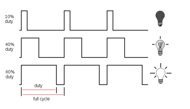
Duty Cycle
In this context, the Duty Cycle indicates what percentage of the time a signal is ON (at logical high - high voltage).
Consider a PWM signal with a 25% duty cycle: it will be on for 25% of the time and off for 75% of the time.
Figuring out the duty cycle is a piece of cake, let’s go over the main components:
- The Time On, Ton, is the amount of time the signal is on (also known as the pulse width)
- The Time Off, Toff, is the amount of time the signal is off
- The total cycle time, Tcycle, is the sum of Ton and Toff
The duty cycle can be calculated as follows:
\[DutyCycle = {\frac{T_{on}}{T_{on}+T_{off}}}\times100\%\]
Period
Indicates the amount of time (usually in milliseconds) for each part of the cycle. The Time On, Ton in the diagram above is the time the signal is high. This is also known as pulse width. Similarly, Time Off, or Toff is the time the signal is low.
The Cycle time corresponds to the overall period of the PWM, or Ton + Toff.
The frequency is the inverse of period:
\[Frequency = {\frac{1}{Period}}\]
For example, a PWM signal with a total cycle time of 20ms has a frequency of 50 Hz. All this means is that the signal will complete 50 full cycles in a second.
How Servos Work
Servo motors are controlled by via a pulse width modulated (PWM) signal. Servo motors usually have three wires: power, ground and the control signal.
Most servos fixedly rotate between 0° and 180° - starting and ending at fixed points relative to the motor. They accept pulses within a fixed range commonly between 500 and 2500us. To put it all together, say we send a 500us width pulse to a servo accepting pulses between 500us and 2500us. The servo will rotate its arm to the 0° position in response - no matter which position the arm was in before. It will respond with appropriate increments when the pulse width is increased up until 2500us, then it will stop moving.
When the servo is receiving signals continuously, it will apply force to attempt to stay in the position that is being signalled. When the servo is unpowered and sent no signals, it won’t actively try to restore position. Manually moving the servo arm is possible when unpowered, but it should not be done as it can damage the servo.
Typical Pulse Width Values
For most servos, providing a 1.5 ms pulse width will place the shaft in the neutral position. Anything greater or less will move the shaft clockwise or counterclockwise. Typical servos can only move 90˚ in either direction from the neutral position. Note that the minimum and maximum shaft positions correspond to minimum and maximum pulse widths, these can vary between servos, so make sure to look at your servo’s datasheet.
The recommended PWM frequency for servos is typically in the range of 40-200 Hz, with most servos using 50 Hz.

For our experiment, we’ll demonstrate how servos can be controlled through PWM signals. We’ll connect them to the Expansion, then write some code to make them rotate. We touched on PWM very briefly before, but to operate servos, we’ll have to go a bit deeper.
Building the Circuit
The PWM Expansion was designed with servos in mind, and its headers allow you to plug standard servos straight into the Expansion. This experiment circuit is relatively simple because you only need to plug the servos into the board. If you haven’t already, it is highly recommended that you read over the PWM Expansion article in our documentation for safety tips.
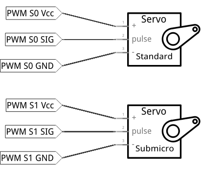
For completeness, here’s a diagram of our circuit:
What You’ll Need
Gather the following from your kit:
- 1x Omega2 plugged into Expansion Dock
- 1x PWM Expansion plugged into Expansion Dock above
- Servo Motors
- 1x Standard Size
- 1x Micro Size
Hooking up the Components
- Plug the PWM Expansion into your Expansion Dock.
- Plug the power cord of the Standard Size servo motor into the
S0channel of the PWM Expansion.- make sure the orange wire from the motor is connected to the pin with the white base on the Expansion!
- Repeat the step above with the Micro Servo connecting to channel
S1.
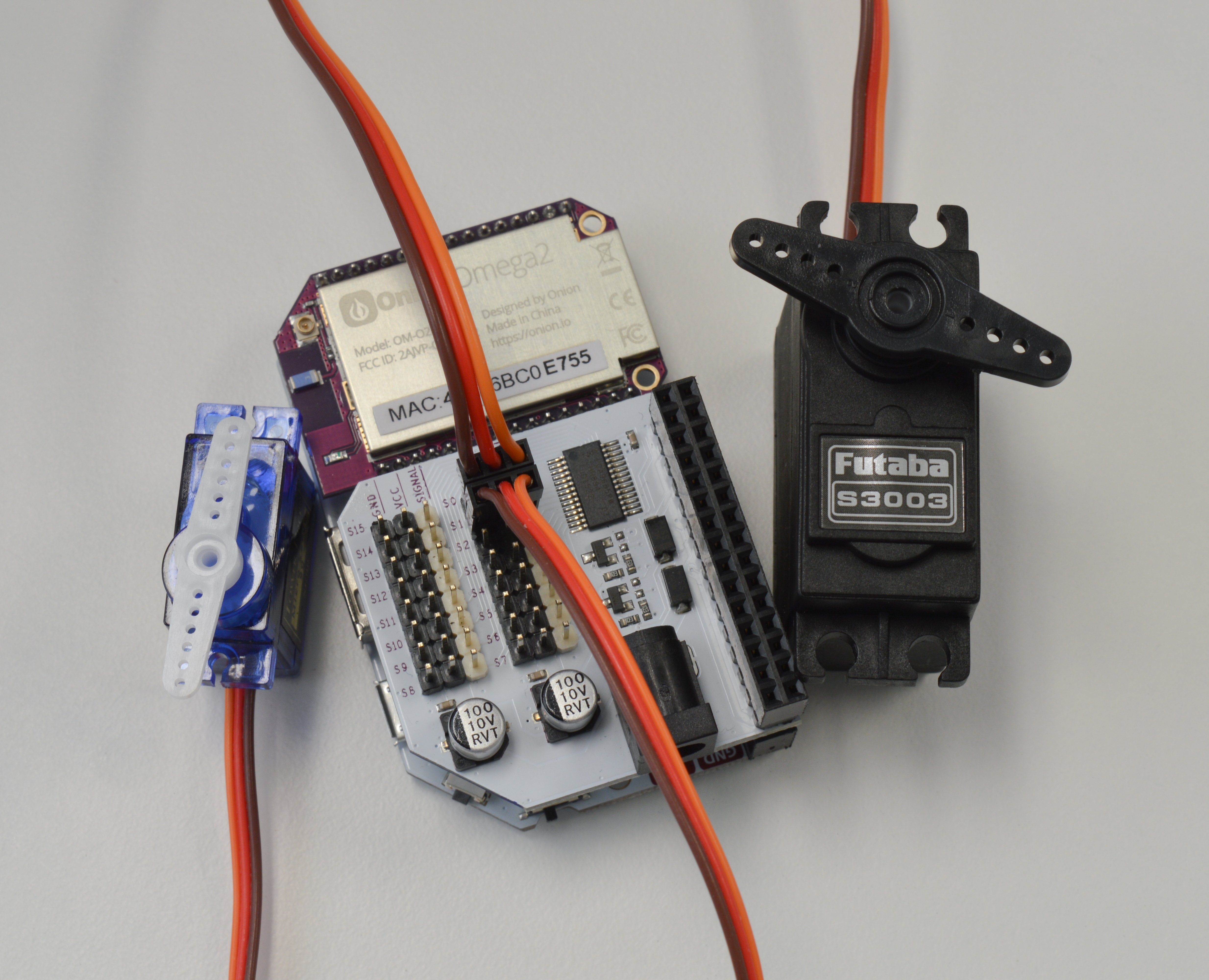
Your circuit should look like this:
Writing the Code
Let’s write another class to represent a servo motor based on the class we wrote in the previous experiment.
Open up motors.py from before and append the following code to it:
# define the minimum and maximum pulse widths that will suit most servos (in us)
SERVO_MIN_PULSE = 1000
SERVO_MAX_PULSE = 2000

# Servo motor
class Servo:
    """Class that uses PWM signals to drive a servo"""

    def __init__(self, channel, minPulse=SERVO_MIN_PULSE, maxPulse=SERVO_MAX_PULSE):
        # initialize a pwm channel
        self.channel = channel
        self.frequency = 50
        self.pwmDriver = OmegaPwm(self.channel, self.frequency)

        # note the min and max pulses (in microseconds)
        self.minPulse = minPulse
        self.maxPulse = maxPulse

        # calculate the total range
        self.range = self.maxPulse - self.minPulse

        # calculate the us / degree
        self.step = self.range / float(180)

        # calculate the period (in us)
        self.period = (1000000 / self.pwmDriver.getFrequency())

        # initialize the min and max angles
        self.minAngle     = 0
        self.maxAngle     = 180

    def setAngle(self, angle):
        """Move the servo to the specified angle"""
        # check against the minimum and maximium angles
        if (angle < self.minAngle):
            angle     = self.minAngle
        elif (angle > self.maxAngle):
                angle   = self.maxAngle

        # calculate pulse width for this angle
        pulseWidth = angle * self.step + self.minPulse

        # find the duty cycle percentage of the pulse width
        duty = (pulseWidth * 100) / float(self.period)

        # program the duty cycle
        ret = self.pwmDriver.setDutyCycle(duty)
        return ret

    def setDutyCycle(self, duty):
        """Set duty cycle for pwm channel"""
        ret = pwmExp.setupDriver(self.channel, duty, 0)
        if (ret != 0):
            print 'ERROR: pwm-exp setupDriver not successful!'

        return ret
Paste the code below into a file called MAK02-servoControl.py, make sure your circuit is set up, then run it and see what happens!
from motors import Servo
import time

def main():
    # instantiate objects for the two servos
    standardServo = Servo(0, 500, 2400)
    microServo = Servo(1, 500, 2400);

    # set both servos to the neutral position
    standardServo.setAngle(90.0)
    microServo.setAngle(90.0)
    time.sleep(2)

    # infinite loop
    while(True):
        # Turn servos to the 0 angle position
        standardServo.setAngle(0.0)
        microServo.setAngle(0.0)
        time.sleep(2)
        # Turn servos to the neutral position
        standardServo.setAngle(90.0)
        microServo.setAngle(90.0)
        time.sleep(2)
        # Turn servos to the 180 angle position
        standardServo.setAngle(180.0)
        microServo.setAngle(180.0)
        time.sleep(2)


if __name__ == '__main__':
    main()
What to Expect
The script will first set the servo motors to the 90 degree (neutral) position. Then it will repeat the following pattern:
- First, the motor shaft move to the
0degree position and stop for two seconds. - Next the shaft will move back to the
90degree (neutral) position and stop for another two seconds. - Finally it will move in the other direction to the
180degree position and stop for another two seconds.
Here it is working in the Onion Lab:
Since the pattern will repeat infinitely, you will need to break by entering Ctrl-C.
Note: It’s highly recommended to turn the oscillator off after terminating the script by running the following in ssh or terminal:
pwm-exp -sThis is because the servos will continue to be sent signals if the oscillator remains on. Although the arms won’t be swinging, the motors will be running needlessly and drain power.
A Closer Look at the Code
In this experiment, we encountered some classic ways to control devices with software. We covered the following techniques and topics:
- Infinite loops - a way to repeat actions over and over again
- Python math - integers, floats, and conversions
- Delays - simple delay
Infinite Loops
As you may know by now, infinite loops in Python (and many other languages) can be implemented with a loop that always evaluates true:
In simple experiments like ours, we can use infinite loops to make sure our program always runs. Other devices such as thermostats, and digital clocks can also be implemented using infinite loops. In these loops, conditions and states can be evaluated over and over again. After the conditions are checked, actions that require those conditions can be performed. For example, a thermostat would evaluate the temperature of the room over and over again. When it detects the temperature to be lower than some value, it can turn on the heat; and if it’s higher than some value, it can also turn off the heat accordingly.
In this example, the loop doesn’t check anything, only progressing through the commands one-by-one. Be prepared for that to change in the upcoming experiments though!
Math in Python
In this code example, you can find integer numbers along with decimal points (eg. 3.0). The reason 3.0 is used instead of 3 is to tell Python to interpret the number as a decimal, or floating point number. This makes it behave like a number in a calculator.
If we dropped the decimal point (simply using 3), we’d be doing integer math. In this case, Python will literally drop the decimal part of any calculation. Sometimes we want this behaviour, such as when counting objects or iterating through loops. But this behaviour can be the source of large errors if you need to do precise calculations!
To see the difference for yourself, we’ll add some fractions together but we’ll write them in what should be equivalent forms. Start the interactive Python interpreter on the command line by simply typing python, then run each of the print commands below:
# simple examples of floating point vs integer math
print 4.0/3
# will print "1.3333333..."
print 4/3
# will print "1"

# difference between floating point and integer math in expressions
print 5.0/3 + 8.0/3
# will print "4.3333333..."
print 5/3 + 8/3
# will print "3"
You can see in the first two examples that the decimal part is dropped from the answer. In the last two you can see this error can carrying forward, causing a huge error!
This applies to many other programming languages due to the way decimal and integer numbers are handled by computers. Be careful!
Timing
As we’ve mentioned in the Starter Kit experiments, the Omega has a microprocessor which executes code extremely quickly (500MHz), while on the other hand servos are mechanical devices and can only react to command changes up to a certain point (50Hz ~ 1kHz). If a program like ours runs on the Omega with no time delays built in, the Omega will change the servos’ PWM signals faster than they can interpret them. This can cause unexpected behaviour; for example, your servos may twitch as they struggle to keep up.
The Python time library and time.sleep() function calls are crucial to make sure there’s enough time for the servo to react to command changes.
Hardware Calibration
In reality, there will always be minor differences in mechanical hardware between motors even if they’re of the same make and model. This can be due to slight variations in manufacturing, how well it was assembled, and so on.
For this reason, sending the same signals to two of the same motor may not cause them to behave exactly the same. The pulse width values we provided - 500 and 2000; 500 and 2500 - are values we’ve found to work with servos in our lab. Try playing around with these and seeing what happens; this process is called calibration.
See if you can use the command line tools or the libraries to figure out what duty cycles correspond to what kind of movement in your own servos!
Manufacturers almost always provide data sheets to let you know the characteristics and limits of your hardware. They’re definitely the best place to start when calibrating.
Going Further
If you want to do more advanced projects like a robot arm or a rover, you should provide an external power supply to the PWM Expansion via the barrel jack. This is because the PWM Expansion draws power from the Expansion Dock’s power circuitry. Heavy loads and multiple servos draw a lot of current, and the high power demand may exceed what the Dock is able to provide.
Also, keep in mind that the Omega cannot be powered directly by this external power supply because the DC barrel jack’s positive voltage connection is isolated from the main power circuitry. For full details, see our PWM Expansion hardware article.
Next time, we spin a motor.