Dimming LEDs
Welcome to the Maker Kit! We hope you’re as excited as we are to get cracking with your fancy Onion Expansions.
In this tutorial, we’ll learn how to control the PWM Expansion with Python, and we’ll use it to control a whopping 16 LEDs. We’ll connect the LEDs to a breadboard, then we’ll write some code to light up the LEDs for a mini light show!
Pulse Width Modulation
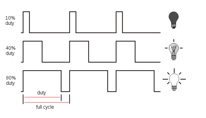
Pulse Width Modulation (PWM) is a technique of producing varying analog signals from a digital source.
Digital signals can only be either HIGH or LOW, where the HIGH voltage is some fixed value depending on the circuit. On the Omega, HIGH on the Omega is 3.3V.
On the other hand, an analog signal can be any voltage between HIGH and LOW. Normally, digital circuits can’t freely vary voltage signals, but they can use PWM to get close enough. It works by repeatedly pulsing a HIGH digital signal on and off so that the average voltage coming from the circuit over time would be equivalent to an analog signal between HIGH and LOW. To change the analog voltage, you can vary how fast the HIGH signal is pulsed.
There are some limitations to this method depending on how the driving circuit is built, but it’s relatively simple to implement and can be accurate enough for most cases.
Let’s quickly review a bit about LEDs:
- LEDs only allow current to flow in one direction. When current flows through them, they light up!
- They are polarized and have two ends:
- The anode, where current enters. Connect this side towards the power rail or high voltage.
- The cathode, where current exits. Connect this side towards the next component in series or ground.
- They need a resistor to limit the current that flows through them; too much will burn them out. At 3.3V, the 200Ω resistors can provide enough resistance.
You can take a quick look at the first Starter Kit experiment for full details.
Building the Circuit
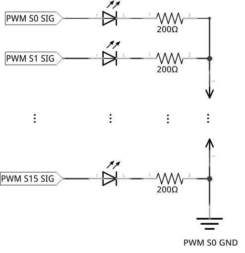
For this circuit, we will connect one LED to each of the 16 channels (0-15) on the PWM Expansion. Using the breadboard here will keep things organized.
We will be building the following circuit:
What You’ll Need
Grab the following from your kit:
- 1x Omega plugged into Expansion Dock
- 1x Breadboard
- 1x PWM Expansion plugged into the Expansion Dock
- 16x LEDs of any color
- 16x 200Ω Resistors
- Jumper wires
- 16x M-F
- 1x M-M
Hooking up the Components
Each LED will be connected to the board in the same way, so we’ll cover wiring a single LED first. Then you can repeat this process for all 16 and you should be good to go.
- Find the anode and the cathode of your LED, make note of which one is where, then plug the LED across the channel of your breadboard on any row you wish (on columns
eandf)- The most reliable way to find the anode/cathode isn’t the length of the pins, it’s by examining the diode inside the plastic head.
- Take a 200Ω resistor and use it to connect the LED’s cathode to the column labelled
-.- We’ll call the
-labelled column theGNDrail.
- We’ll call the
- Now connect the
GNDrail to theGNDpin on channelS0of your PWM Expansion with one M-M jumper - Find the signal pin of any channel. We’ll start at channel 0 (
S0on the PWM Expansion).- The signal pin is marked by a white plastic base. For channel
S0, it should be clearly labelled asSIGNALto the left side. We’ll call this theSIGpin.
- The signal pin is marked by a white plastic base. For channel
- Connect the
SIGpin to a pin in columnain one of the rows on the left side of the breadboard using a M-F jumper wire. (eg.1a)- We’ll start at row 1 for the first one, and so on.
If your circuit now looks like this:
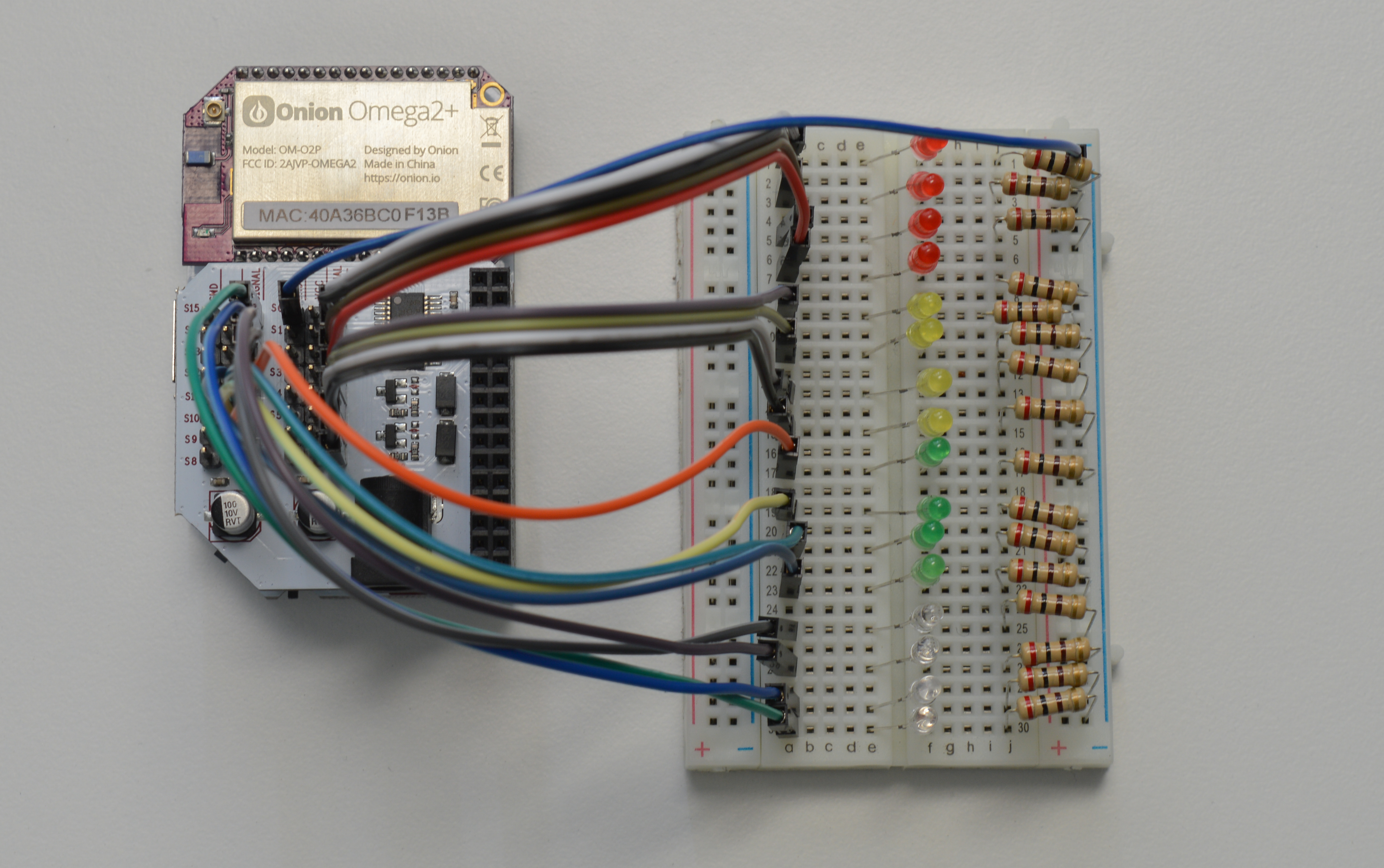
Then we’re all set!
Writing the Code
Let’s write a class to abstract methods for a PWM pin on the Omega. Create a file called motors.py and paste the following code in it:
from OmegaExpansion import pwmExp

class OmegaPwm:
    """Base class for PWM signal"""

    def __init__(self, channel, frequency=50):
        self.channel     = channel
        self.frequency     = frequency

        # check that pwm-exp has been initialized
        bInit     = pwmExp.checkInit()

        if (bInit == 0):
            # initialize the Expansion
            ret     = pwmExp.driverInit()
            if (ret != 0):
                print 'ERROR: pwm-exp init not successful!'

            # set to default frequency
            self._setFrequency(self.frequency)

    def _setFrequency(self, freq):
        """Set frequency of pwm-exp oscillator"""
        self.frequency     = freq
        ret     = pwmExp.setFrequency(freq);
        if (ret != 0):
            print 'ERROR: pwm-exp setFrequency not successful!'

        return ret

    def getFrequency(self):
        """Get frequency of pwm-exp oscillator"""
        return self.frequency

    def setDutyCycle(self, duty):
        """Set duty cycle for pwm channel"""
        ret     = pwmExp.setupDriver(self.channel, duty, 0)
        if (ret != 0):
            print 'ERROR: pwm-exp setupDriver not successful!'

        return ret
Now let’s write the script for the experiment. Create a file called MAK01-pwmLed.py and throw the following code in it. Then run it and keep an eye on your LEDs:
from motors import OmegaPwm
import math
import time

# define constants
PWM_FREQUENCY = 1000
sleepTime = 0.005

# apply sine to the input radian value
#    ensure that it
def calcDutyCycle(rad):
    result = 50.0*(math.sin(rad)) + 50.0
    if(result > 100.0):
        result = 100.0
    if(result < 0.0):
        result = 0.0
    return result

# main function
def main():
    # construct an array of OmegaPwm objects
    ledObjectArray = []     # create an empty array
    for i in range(16):
        # instantiate an object tied to the i channel on the PWM Expansion
        obj = OmegaPwm(i, PWM_FREQUENCY)
        # add the object into our array of objects
        ledObjectArray.append(obj)

    # define the phase difference (in radians) between each channel
    channelIncrement = (2 * math.pi)/16
    # define the phase difference (in radians) for each
    phaseIncrement = (2 * math.pi)/160

    # counters for frames and duty cycles in the LED animation
    loopCount = 0
    duty = 0

    # infinite loop
    while(True):
        # loop through each of the LED PWM Channels
        for index,element in enumerate(ledObjectArray):
            # calculate the duty cycle for the channel using a sine function
            #   the input to the duty cycle calculation consists of the sum of two numbers, one fixed and one changing:
            #   - multiplying channelIncrement by the PWM channel index - fixed for each channel
            #   - multiplying phaseIncrement by the loop count - changing
            duty = calcDutyCycle(( (index) * channelIncrement ) + (loopCount * phaseIncrement))
            element.setDutyCycle(duty)
        # increment the loop count and ensure it doesn't go over 160
        loopCount += 1
        loopCount = loopCount % 160
        # add a small delay for the visual effect
        time.sleep(sleepTime)

if __name__ == '__main__':
    main()
What to Expect
You should see a wave like effect across the LEDs when they are placed beside each other in order from 0 to 15.
This code uses an infinite loop, so you’ll have to terminate the script with Ctrl-C.
A Closer Look at the Code
The basic structure of our experiment goes as follows:
- First, we create a generic class to control one PWM channel.
- In our main function, we create an object for each PWM channel from the class above.
- We then set each channel’s duty cycle using their
setDutyCycle()function.
Some points of interest here:
- Creating objects from classes
- Using the PWM Python Module
- Using sinusoidal waves
This experiment makes use of several mathematical operators. If you need a refresher, here’s a cheat-sheet of what do the operators do:
| Operator | Effect |
|---|---|
a * b |
Multiplies a and b |
a / b |
Divides a by b |
a % b |
Returns the remainder of a divided by b (“modulo”) |
math.sin(a) |
Returns the sine of a, where a is in radians |
math.pi |
Returns the value of pi |
a += b |
Assigns the value of a plus b to a |
We will explain the sine function in the following sections.
Creating a Class
As a refresher, Python is an Object Oriented programming language.
In Object Oriented Programming, classes are blueprints or abstractions of code. An object is a copy of data and/or functions created from a class blueprint. In a program, you can create as many copies (objects) of a class whenever you need to!
For example, you can write a class for a “four sided shape” that contains data for length and width. You can then use it to create objects such as a “square” or a “rectangle”. Creating an object from a class is called instantiation, and objects created from a class are called instances.
To see another example of classes in Python, check out the shift register article where we first introduced them.
In our case, we used the class OmegaPwm as a blueprint for a single PWM output channel. By creating objects of this class, we can represent and control an individual PWM channel on the board. When we call the OmegaPwm() function with arguments i and PWM_FREQUENCY, we’re initializing objects of the OmegaPwm class for each channel i on the Expansion. Once we instantiate each channel object we store the objects inside of a list, such that their index corresponds to the channel number. This makes the rest of our code a little simpler, as you’ll soon see below.
Using the Onion PWM Expansion Python Module
Python’s functionality can be expanded with modules and packages - like extra lego sets allowing you to build more complex things. Here we use the PWM module (pyPwmExp) to control the PWM Expansion. The module comes with a set of functions to control and modify the PWM Expansion channels and properties. By running a script to control the Expansion, you don’t need to manually need to enter or trigger any commands through the terminal. You can simply leave it running, and it would automatically do its job!
You can find a detailed guide to this module in the pyPwmExp library reference in the Onion docs.
Specifically, we use the following functions:
setFreqency()setupDriver()checkInit()driverInit()
Controlling the PWM Outputs
In omegaPwm.py, you’ll notice the servo frequency was set to 1000 Hz. This is to ensure the LED doesn’t flicker no matter what duty cycle we set the channel to output. This is done in the class’ constructor function by passing PWM_FREQUENCY as the 2nd argument. For each channel, we can change the duty cycle on the fly by calling setupDriver() and sending in the channel, and the duty cycle (recall that this is between 0% and 100%). By changing the duty cycle, we change the average voltage sent to the LED connected to the channel - this is how the LEDs dim and brighten.
Instantiating an OmegaPwm object requires a channel number and frequency. Note that if you change the oscillator frequency of one channel (through initialization or setFrequency()), you change it for all channels. This is because the PWM Expansion only has one oscillator shared between all the outputs.
Initializing the PWM Expansion
If you look at the constructor (the __init__ function), you will notice the line:
This line initializes the PWM Expansion for usage. This starts the oscillator on the PWM Expansion which actually produces the signals sent through the pins. Without this line, the oscillator will be off and will not produce any PWM signals!
Before we initialize the oscillator, we can check if it’s already on with pwmExp.checkInit(). By checking the return value we can avoid initializing it multiple times. For the PWM Expansion in particular, initializing it multiple times doesn’t really matter much. However initialization for other hardware devices may take quite a while, so it’s a pretty good habit to get into to save you some time.
The Math Behind the Duty Cycle
You’ll notice a lot of mathematical operations going on with the math module in Python. Combined, this allows the brightness of the LEDs to vary sinusoidally.
If you’re not familiar with what “sinusoidally” refers to, a sine wave is a type of smooth wave that goes up and down over time. The sine function is based on the vertical component of a line that goes from the center of an imaginary circle to its edge. When you rotate the line by an angle (like the hands on a clock), the length of the vertical component will change. You can see an example of one in the graphic below:
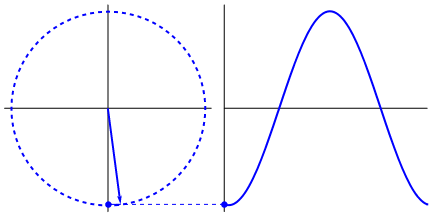
The sine function takes an angle and returns a value between -1 and 1. To convert it to a duty cycle, we then multiply the value by 50, bringing the maximum range to -50 and +50. We then add 50 to the final value so that it will now be between 0 and 100.
In every frame, for each channel, we calculate the duty cycle by doing the following:
- The duty cycle value is based on the sine of the angle we pass it. The angles are in units called radians.
- The sine function’s values will start repeating every 360 degrees or 2π radians, because it’s going around a circle.
- Before the infinite loop, we offset each PWM channel’s starting duty cycle to be evenly within 2π radians (a full circle).
- The lights will always be
channelIncrementapart from each other.
- The lights will always be
- Each time the infinite loop executes, the radian values for the channels will be incremented by
phaseIncrement.- We added a modulo operation to the loop counter; once it has iterated 160 times, the counter will reset to 0 and start again.
- This is to prevent increasing the loop counter to infinity! Well, it wouldn’t reach infinity, but unexpected things might start happening.
We then pass the calculated duty cycle to the setDutyCycle() function, which sets the LED’s brightness.
The code in the for loop in the main() function is equivalent to the block below:
    for loopCount in range(0,160):
        for index in ledObjectArray:
            duty = calcDutyCycle(( (index) * channelIncrement ) + (loopCount * phaseIncrement))
            ledObjectArray[index].setDutyCycle(duty)
Python’s built in mathematical operations are pretty powerful, but they do have some pitfalls which we’ll cover in the next experiment.
Next time, we will control servos with the PWM Expansion.