Controlling a DC Motor using an H-Bridge
For this expriment, we’ll be controlling a motor using the PWM Expansion. To do this, we’ll be using an H-Bridge chip and sending it the appropriate control signals with the PWM Expansion, the H-Bridge will then take care of running the motor. Along the way, we’ll learn exactly how H-Bridges work and create more classes that take advantage of the ones we’ve made previously. To expand on that, we’ll hook up three switches and program the Omega to control the speed and direction of the motor based on their positions.
If you need a refresher on how PWM (or Pulse-Width Modulation) works, you can find an explaination in the first dimming LED expriment.
How DC Motors Work
The simplest of all motors, DC motors turn when a DC voltage is applied across it. This kind of motor can be found in drones, power tools, and robots. A DC motor can change speend and direction depending on how much power is fed to it and in which direction.
The DC motor uses the uses a magnetic field generated by the by an electromagnet to turn the armature of a motor. The electromagnet is activated by applying voltage, so when the power is on, the magnetic field it generates will cause the armature (a coil of wire) to generate its own nagmetic field, these fields push eachother away and cause the armature to spin.
To get the motor to spin the other way, we need to reverse the applied voltage, meaning the flow of current through the motor will be reversed. Unfortunately switching the direction of current from a controller like the Omega is difficult. The processors use low current and voltages, plus they are usually disconnected from the motor to prevent inductive feedback distrupting their operation.
If only there was some kind of device that can help us control the power we supply to our DC motors…
Note that applying current to both terminals can cause damage to the motor.
How H-Bridges Work
An H-Bridge is a circuit that allows voltages to be applied across a load in either direction. Electric current flows from the source to ground, and many components need to be oriented according to the direction of current to work as expected. An H-Bridge is a circuit built to change the direction of the voltage and thus the current flowing to a load.
In electrical terms, a load is any piece of a circuit that consumes electric energy to do things - heating, turning, lighting up, and so on.
An H-Bridge is made up of four switches: two in series, and two in parallel, with the load placed in between the switches. In this configuration the circuit takes an “H” shape.

In order to change the direction of the voltage supplied, the H-Bridge controls the switches that deliver power to the load (S1). Looking at the diagram, if we close S1 and S4 while leaving the rest open, the voltage will be applied from left to right across the motor. If S2 and S3 are closed instead and the others open, the voltage will be applied from right to left.
This configuration has potential to create a short circuit, so most H-Bridges do not allow direct control of these switches.
Typical Applications
A few of the typical applications of H-Bridge circuits: * Construct AC (Alternating Current) from a DC source by using a PWM signal to control the H-Bridge. This is a process known as power inversion. * Provide the ability to reverse current across a DC motor, allowing for rotation in either direction.
Additionally, H-Bridges allow loads to be powered independently from the control signals that are controlling them, providing circuit isolation.
The way a PWM signal operates a motor is by switching the power supply on and off really quickly. Normally this can be done sending the PWM signal to a transistor, and have the transistor switch ther power supply. By varying the pulsewidth of the PWM signal, the speed of the motor can be controlled. An H-bridge can replace the transistor and add functionality by allowing the direction of the current to be easily changed. We still send a pulsating signal to the H-bridge in order to control the speed, except now we can switch the direction of the current flow by changing which switches are open.
In our circuit, we’ll be using an H-bridge Integrated Circuit (IC) chip so we don’t need to wire the internals ourselves, and to prevent short circuits that could arise if we directly controlled those switches.
If you want to start building right away, skip ahead to the next section. If you’d like to know how the signals from our code will control the motor, read on!
The SN754410 H-Bridge Chip
The SN754410 chip contains two H-bridges, giving us four outputs, thereby allowing us to control two DC motors. For now, we’ll just be controlling a single motor.
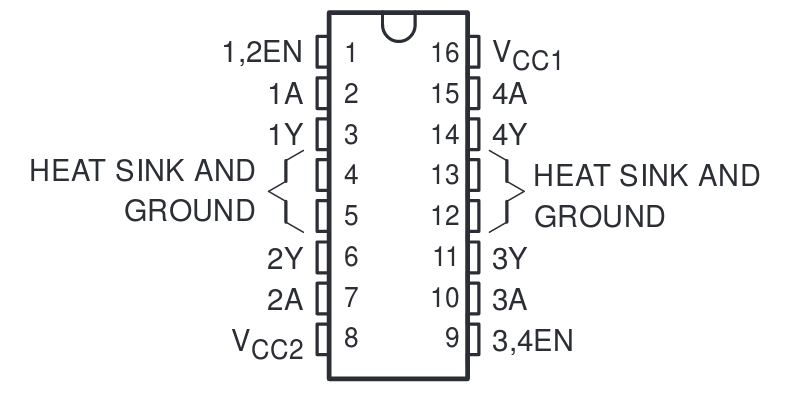
So instead of switches 1/2/3/4, we’ll be switching 1A and 2A (as seen in the datasheet). For this tutorial, we’ll be using one of the two H-bridges to control power sent to the two inputs of your DC motor. Specifically, the pair of inputs and outputs (1A, 2A and 1Y, 2Y) on the left side of the chip.
On the chip, 1A controls the polarity of 1Y, same goes for 2A and 2Y. At a very high level, this H-bridge chip changes the output voltage (to the pins labelled Y) according to the input voltage sent to the pins labelled A. For example, sending a ‘high’ to 1A will send the same to 1Y. The difference is the signal sent out to Y pins use the voltage supplied to pin 8 regardless of what the input voltage is.
Voltage acts kind of like a waterfall - it always sends the current flowing from the voltage source (top) to the ground (bottom). You can think of the source as HIGH and ground as LOW. So if you connect a motor to 1Y and 2Y, it’ll only move if they’re sending out different signals.
The 1,2EN pin simply turns the H-bridge on or off. If 1,2EN sees a ‘high’, then everything we’ve covered above happens as normal, if it’s off, then there won’t be anything sent to the outputs no matter what 1A and 2A are set to.
By implmenting the H-Bridge in this way - with two switches instead of four independent ones - the chip conveniently handles short circuit situations and simplifies the operation of an H-bridge.
Building the Circuit
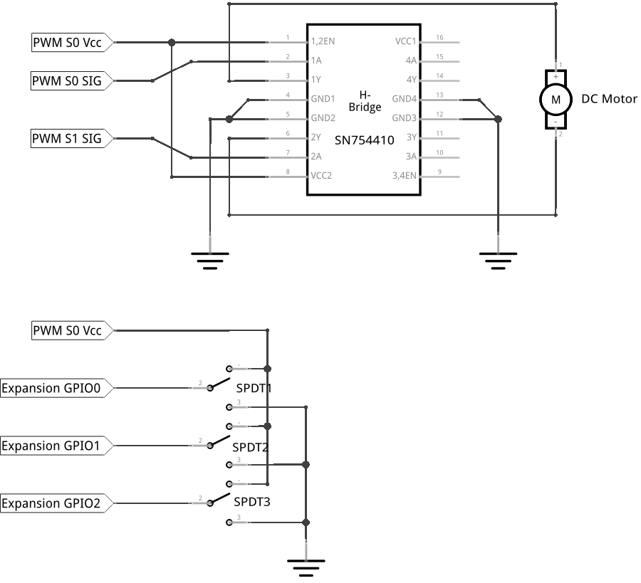
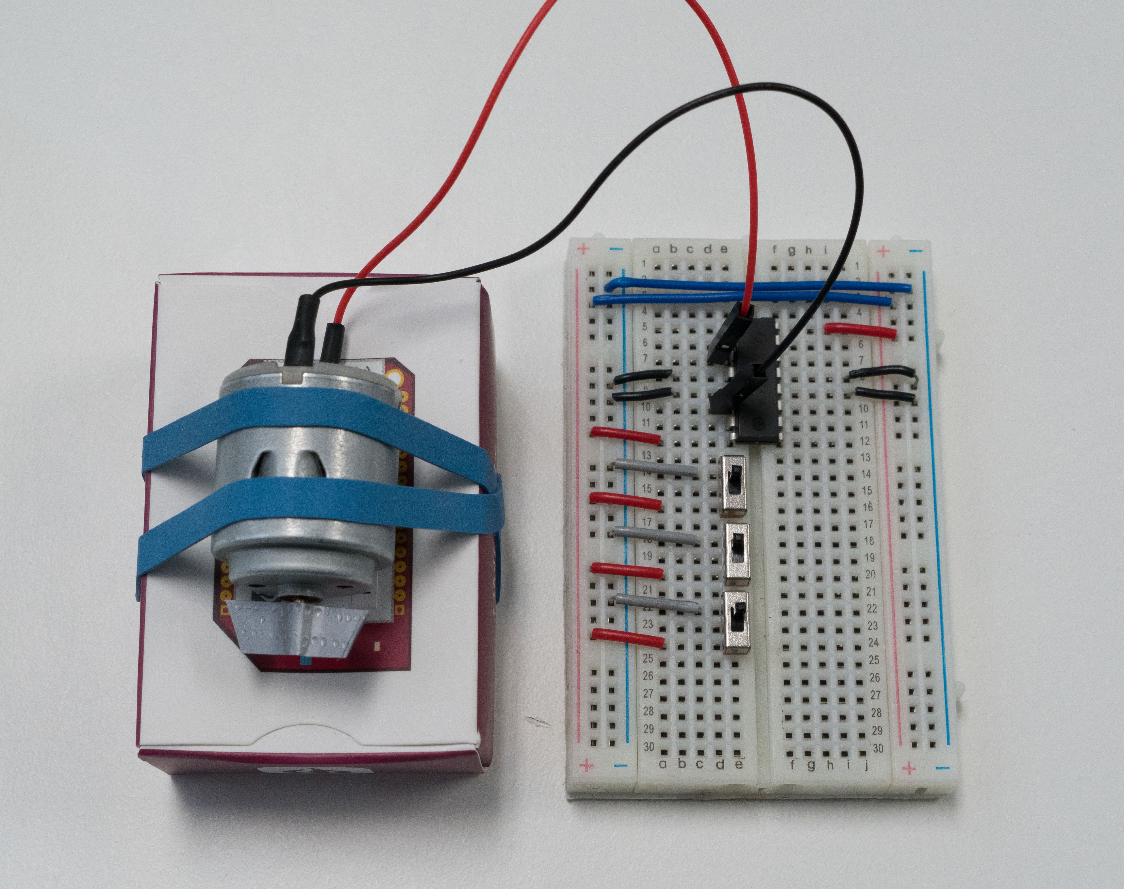
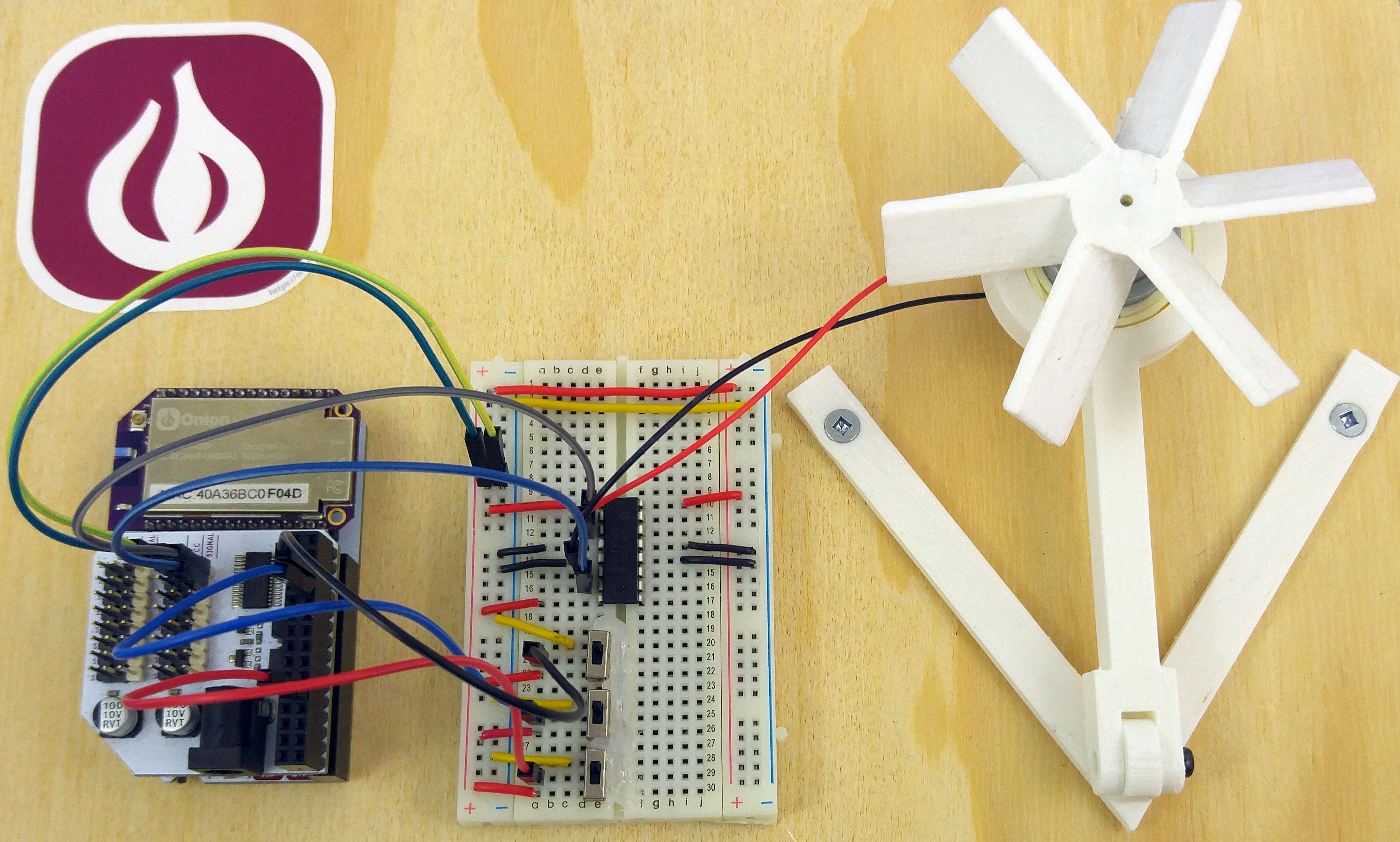
This circuit will connect the Omega to a DC motor. The Omega will first be connected to the PWM Expansion, the PWM Expansion will be sending signals to an H-bridge, which will deliver power to the DC motor according to the signals. The PWM will signal how fast the motor should turn and the H-bridge acts as a switch - turning the supply voltage on or off according to the PWM signal.

In the pictures, you’ll see some shorter wires, these we used instead of jumpers to give you a better picture of what’s going on. To more easily see the rotations of the motor, we wrapped some duct tape around the motor axle.
Note: As can be seen above, the chip is roughly mirrored. The top right and bottom left pins are the power supply for the outputs (pin 8) and the chip (pin 16) respectively. The difference between the two power pins is the voltage supplied to the outputs can be up to 36V, while the voltage supplied to the chip is recommended to be within 2~5V. If you want to power a large motor, you should power the motor with the external supply through pin 8 and supply around 3V to pin 16.
Here’s a diagram to refer back to if things get hectic:
What You’ll Need
You may need a couple of rubber bands and a block to hold down the DC Motor when it’s running. Altogether, this is what you’ll be using to make the circuit:
- 1x Omega2 plugged into Expansion Dock
- 1x PWM Expansion plugged into Expansion Dock above
- 1x DC Motor
- 1x H-bridge (has “SN754410” on top of the chip)
- 1x Breadboard
- 3x SPDT switches
- Jumper wires
- 4x M-F
- 18x M-M
Hooking up the Components
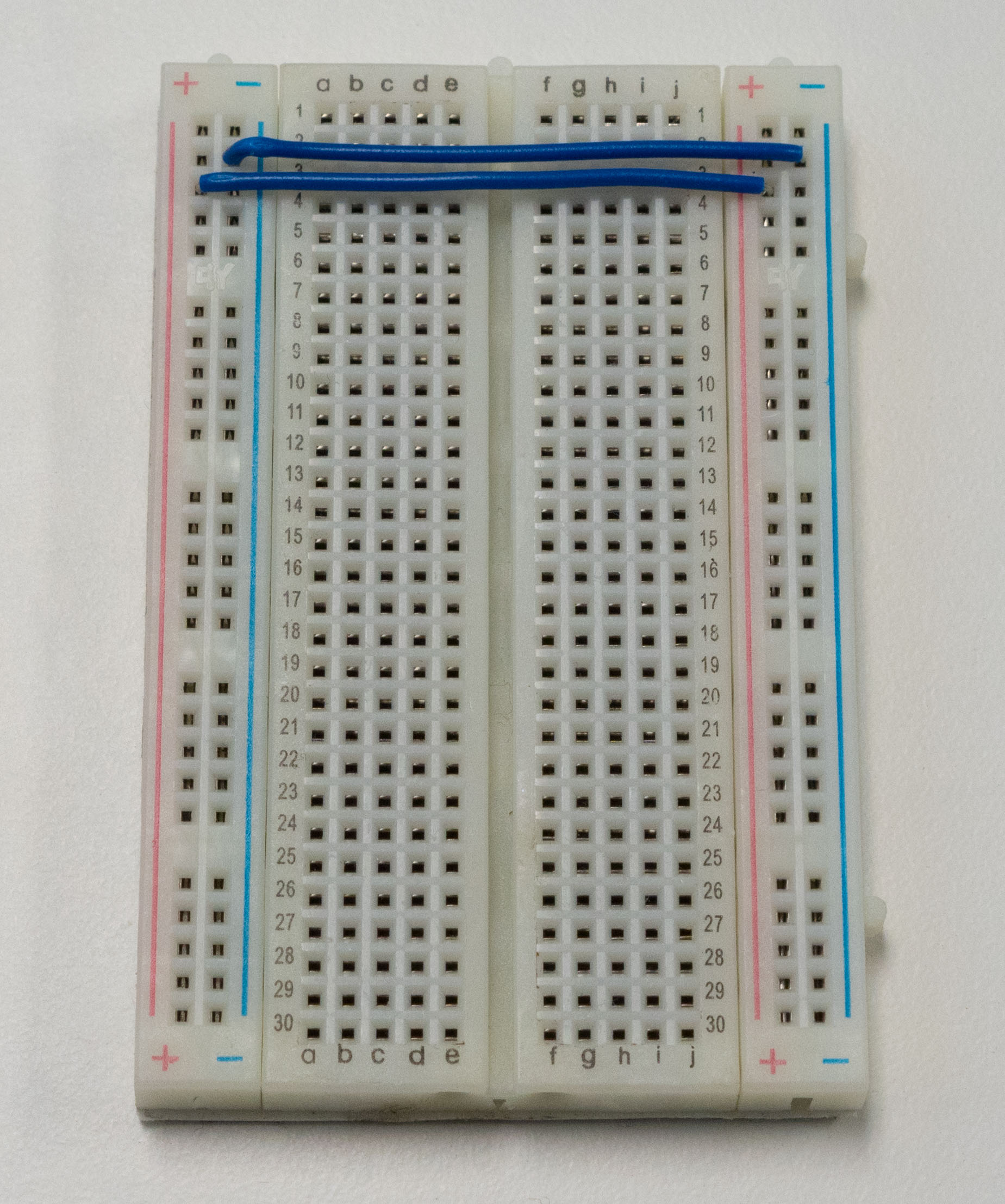
When working with ICs, setting up the breadboard’s rails can be very helpful in reducing clutter. For this expriment, we’ll do this first to reduce the wires needed.
- Connect the negative (
-) rails on either side of the board together on one end (usually the end away from most of the wiring) with a M-M jumper, we’ll call this theGNDrail. - Do the same with the positive (
+) rails, we’ll call theseVccrails in this expriment.
Now let’s set up our Circuit:
- Grab your H-bridge, pick a location on your breadboard and plug the H-bridge across the channel in the middle of your breadboard. It should be sitting across with one side in column E and the other in column F, with the half-circle cutout pointing toward the end of the breadboard. We picked rows 5 to 12 in our breadboard.
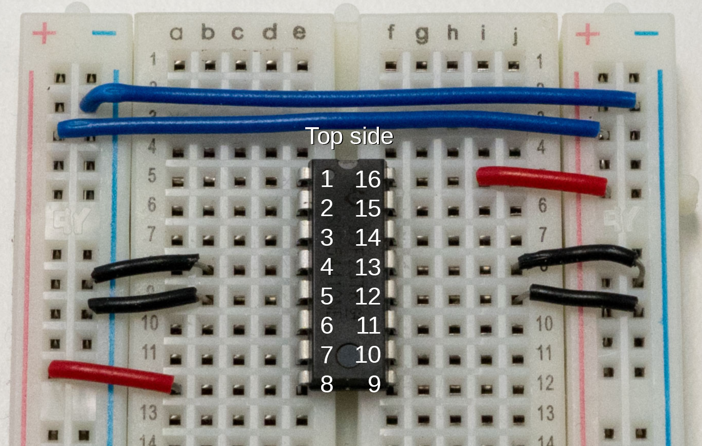
- Take note of which number each pin is from the diagram above - if you’re lost, always look for the little half circle cutout on the chip denoting the ‘top’ of the H-bridge to orient it correctly.
- This is important, you can damage the H-bridge if it’s not wired correctly!
- Let’s connect first connect all the ground connections - pins
4,5,12, and13on the H-bridge are are all grounding pins, so let’s connect those to theGNDrail on their respective sides using four M-M jumpers. We used short wires here to make sure you can see what’s going on.
- Now it’s time to connect the motor to the H-bridge, the motor should have two wires with male pin connectors, one red and one black. They’ll be connected to the pins on the H-bridge through the breadboard.
- Connect the white wire to
1Yof the H-bridge (row 7 on our breadboard). - Connect the black wire to
2Yof the H-bridge (row 10 on our board).
- Connect the white wire to
- Next, we’ll set up the switches - we’ll use them to control what digital signals are sent to the PWM Expansion, and in turn the motor through the H-bridge:
- Pick three sets of three rows (we used row 14 to 24)
- Plug your switches into the rows, three rows per switch - each switch needs a half-row of clearance between the next switch if you want to put them side-by-side.
- With 6 M-M jumpers, connect the leftmost row of each switch to
GNDrail, and the rightmost row of each switch toVccrail.
Now that the H-bridge circuit is done, let’s connect the whole thing to your Omega so it can control the motor:
- We’ll ground the circuit by connecting the
GNDrail to theGNDpin on channelS0on the PWM Expansion with one M-F jumper. - Using 3 M-M jumpers, connect the center row of each switch to Omega GPIO0, GPIO1, and GPIO2 on the Expansion Headers. Make sure you remember which is which, since these will control your motor later!
- Take one M-M jumper and connect
1,2ENon the IC (row 5 on our board) to theVccrail. - Using two M-F jumpers,
- Connect
1A, or row 6 on our board, to channelS0. - Connect
2A, or row 11, to channelS1.
- Connect
- Last but not least, we’ll set power to the Vcc rail by connecting the dangling end of the Vcc (red) jumper to the
Vccpin of channelS0of the PWM Expansion.
Here’s what it looks like when it’s all wired up:
Wiring Precautions
You may have noticed that we wired up all of the breadboard components and GPIO connections first before connecting the main power line. We do this to minimize the risk of making wiring mistakes and powering a circuit that could potentially damage the components or the Omega. This is good practice and we’ll be building circuits in this way throughout these experiments.
If you really want to make sure that your components are safe before performing an experiment, you can leave the Omega turned OFF before connecting power to the circuit. Once everything is connected, you can then turn the Omega on again.
There is a reason we use the
GNDandVccpins on the PWM Expansion instead on the header pins from the Dock. If it’s connected to the header pins, the motor will feedback voltage to the Expansion Dock. This can cause a boot-loop or other unpredictable behaviour with the omega. The PWM Expansion’sVcc/GNDpins have circuit breaking diodes in place to prevent this.
Writing the Code
Let’s add a class definition for a DC motor controlled by an H-bridge to the motors.py file we made in the previous expriment. This class definition will specifically drive a DC motor hooked up to an H-bridge. It builds on the abstractions in the OmegaPwm class and takes care of the details in operating the motor.
Open up motors.py from the Dimming LEDs experiment and add the following:
H_BRIDGE_MOTOR_FORWARD = 0
H_BRIDGE_MOTOR_REVERSE = 1

class hBridgeMotor:
    """Class that two digital signals and a pwm signal to control an H-Bridge"""

    def __init__(self, pwmChannel, fwdChannel, revChannel):
        # note the channels
        self.pwmChannel = pwmChannel
        self.fwdChannel = fwdChannel
        self.revChannel = revChannel

        # setup the objects
        self.pwmDriver = OmegaPwm(self.pwmChannel)
        self.pwmDriver.setDutyCycle(0)
        self.fwdDriver = OmegaPwm(self.fwdChannel)
        self.fwdDriver.setDutyCycle(0)
        self.revDriver = OmegaPwm(self.revChannel)
        self.revDriver.setDutyCycle(0)

        # set the constraints
        self.minDuty = 0
        self.maxDuty = 100

    def setupMinDuty(self, duty):
        """Set the minimum allowed duty cycle for pwm"""
        self.minDuty = duty

    def setupMaxDuty(self, duty):
        """Set the maximum allowed duty cycle for pwm"""
        self.maxDuty = duty

    def reset(self):
        """Set the PWM to 0%, disable both H-Bridge controls"""
        ret =  self.pwmDriver.setDutyCycle(0)
        ret |= self.fwdDriver.setDutyCycle(0)
        ret |= self.revDriver.setDutyCycle(0)

        return ret

    def spin(self, direction, duty):
        """Set the PWM to the specified duty, and in the specified direction"""
        ret = 0

        # 0 - forward, 1 - reverse
        if (direction == H_BRIDGE_MOTOR_FORWARD):
            self.revDriver.setDutyCycle(0)
            self.fwdDriver.setDutyCycle(100)
        elif (direction == H_BRIDGE_MOTOR_REVERSE):
            self.fwdDriver.setDutyCycle(0)
            self.revDriver.setDutyCycle(100)
        else:
            ret = -1

        if (ret == 0):
            # check against the minimum and maximium pwm
            if duty < self.minDuty:
                duty     = self.minDuty
            elif duty > self.maxDuty:
                duty     = self.maxDuty

            # program the duty cycle
            ret = self.pwmDriver.setDutyCycle(duty)
        return ret

    def spinForward(self, duty):
        ret = self.spin(H_BRIDGE_MOTOR_FORWARD, duty)
        return ret

    def spinReverse(self, duty):
        ret = self.spin(H_BRIDGE_MOTOR_REVERSE, duty)
        return ret
Next, let’s write the code for the experiment. This code will get the motor to actually do stuff using the hBridgeMotor class we’ve made above. The script will ask you to enter some numbers, and drives the motor based on your input!
Create a file called MAK03-hBridgeExperiment.py and paste the following code in it:
from motors import hBridgeMotor
import onionGpio
import time

# setup PWM Expansion Channels connected to H-Bridge IC
H_BRIDGE_1A_CHANNEL = 0
H_BRIDGE_2A_CHANNEL = 1
H_BRIDGE_12EN_CHANNEL = 2

# instantiate gpio objects for our switch inputs
directionGPIO = onionGpio.OnionGpio(0)
speed1GPIO = onionGpio.OnionGpio(1)
speed2GPIO = onionGpio.OnionGpio(2)

# create a dictionary of functions against which to check user input
# this is basically a dispatch table to map function calls to different names
motorCommands = {
    '000': (lambda motor: motor.reset()),
    '001': (lambda motor: motor.spinForward(50)),
    '010': (lambda motor: motor.spinForward(60)),
    '011': (lambda motor: motor.spinForward(70)),
    '100': (lambda motor: motor.reset()),
    '101': (lambda motor: motor.spinReverse(50)),
    '110': (lambda motor: motor.spinReverse(60)),
    '111': (lambda motor: motor.spinReverse(70)),
}

def main():
    # instantiate the motor object
    motor = hBridgeMotor(H_BRIDGE_12EN_CHANNEL, H_BRIDGE_1A_CHANNEL, H_BRIDGE_2A_CHANNEL)
    command = '000';

    # loop forever
    while(True):
        # sleeps for a bit to accomodate switches
        time.sleep(0.5)

        # gets the signals going through the switches
        commandNew = directionGPIO.getValue()[0]
        commandNew = commandNew + speed1GPIO.getValue()[0]
        commandNew = commandNew + speed2GPIO.getValue()[0]

        # parses the command into motorCommands format
        commandNew.replace('\n', '')

        # check user input against dictionary, run the corresponding function
        #   but only if the command has changed, no need to keep calling the same command
        if (command != commandNew):
            command = commandNew
            motorCommands[command](motor)


if __name__ == '__main__':
    main()
What to Expect
When run, the script starts the PWM oscillator, and then sets the output to be enabled (channel 0 to 100% duty). Then the script will ask you for a set of 3 digits, the first one sets the direction of the motor, the next two digits set the speed. The program will repeated ask for input, and adjust the speed and direction accordingly.
| Position | Code | Result |
|---|---|---|
| First digit | 0 | Motor turns clockwise |
| 1 | Motor turns counter clockwise | |
| Last two digits | 00 | off |
| 01 | 50% speed | |
| 10 | 60% speed | |
| 11 | 70% speed |
Here it is in action:
As you’ve probably seen before, we use an infinite loop here, and you can break it by hitting Ctrl-C.
Note: We recommend setting the motor to 000 before breaking the loop to avoid damaging the motor. As a reminder, you can simply call pwm-exp -s to stop the motor in the terminal or ssh.
A Closer Look at the Code
In this expriment, we put together knowledge from the previous expriments to control a DC motor with Python. We’re now receiving user input interactively, allowing us to change the output in real-time. On top of that we we used a lookup table to track and translate the input from the user into the output sent to the controller.
Receiving User Input
Here we started to interactively obtain input in a very controlled way. Each switch has two states - 1/ON/HIGH and 0/OFF/LOW. So for three switches there’s 2^3 = 8 differt states of the switch system. This means that we really only have to account for 8 separate input cases.
Unfortunately it’s not always this easy, and it’s good practice to assume all kinds of different inputs can be recieved. Here a good deal error checking happens right at the start of the interaction by limiting the number of input states that are available - we only have three switches. If we allowed users to enter arbitrary commands, we would have to do a lot more validation.
Lookup Tables
You may notice that the input given by the user in the main loop is always checked against the motorCommands variable - this variable stores a set of known values to be checked against. In our case, the table contains valid switch input matched with its corresponding output - also known as a key-value pair - and the script sends out the output to the PWM controller if the input obtained from the user matches any value in the table.
By checking input against a lookup table before sending commands, we can guarantee that no erroneous commands are sent. Couple this with proper calibration and we can greatly reduce the risk of operating hardware remotely.
Limits of PWM Motor Control
DC motors rely on an applied voltage to run, and using PWM means the motor is actually being ‘tapped’ by a series of pulses. Sort of like pushing a box to make it move versus tapping it really quickly. Just like there’s a minimum amount of force needed for a tap to get a box moving, there’s a limit to how short each tap can be before the the motor won’t to react to it.
That is to say, if the pulsewidth is below a certain threshold, the motor won’t start. In testing, the pulsewidth needed to start the motor is somewhere around 10ms - about 50% duty at 50Hz.
Try out different motor settings and see how it behaves. If you’re testing a project with motors and want to slow it down to debug, keeping the limitations of PWM motor control in mind can save you a lot of time!
Next time, we write text to a screen.