Reading a Switch
So far, we’ve been using a program to control GPIOs. Let’s try using physical user input to control our software!
We’ll be using a slide switch as an input to control whether an LED should be turned on or off.
First, we’ll make a simple circuit to figure out how the switch works. Then we’ll connect the switch to your Omega, and control the LED using the Omega as the brain!
GPIOs as Inputs
Now let’s talk about the I in GPIO: using GPIOs in the input direction. This will allow you to read the logical level of circuits that are connected to the Omega.
This leads to two situations:
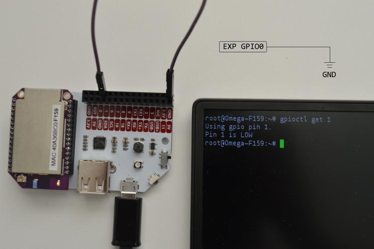
- If a signal is connected to an input GPIO and its voltage is 0V, the Omega will read a logic low
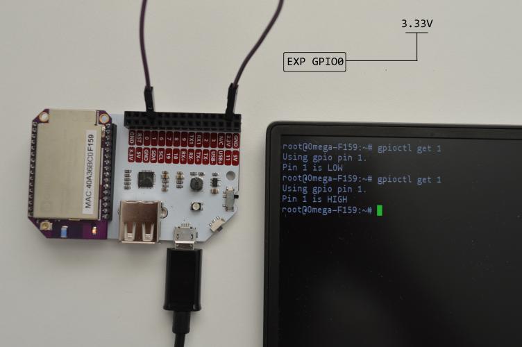
- If a signal with a voltage of around 3.3V is connected to an input GPIO, the Omega will read a logic high.
Using GPIOs in the input direction, allows us to sample the state of any circuit connected to the Omega. As you’ll see, this is going to be very useful.
Switches
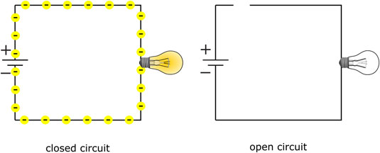
Using a switch, you can turn a circuit on and off. What the switch is really doing is closing and opening the circuit.
An open circuit means there is a gap in the circuit, so current from the power supply cannot flow around the circuit and anything connected to the circuit will be off. When you turn off a lamp, you are opening the circuit; no more current flows to the lightbulb and it stops emitting light.
In a closed circuit, the circuit has no gaps and current can flow freely, any connected component will be received current and will be on. Going back to our lamp, when you switch it on, you are closing the circuit; allowing current to flow to the lightbulb so it can light up your space.
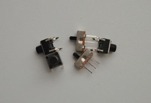
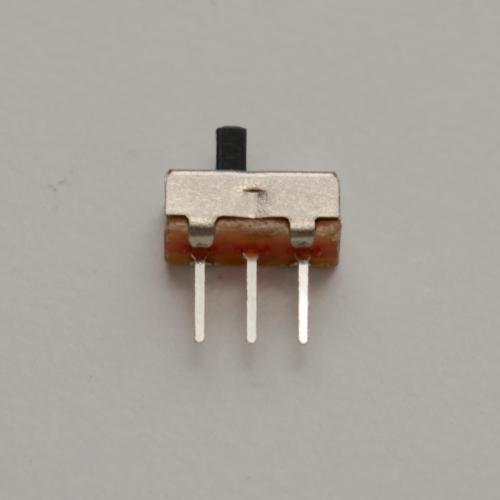
Slide Switches
A three-terminal slide switch like the one included in your kit is commonly used in electronics. It’s what’s known as a SPDT switch, this stands for Single Pole Double Throw. All this means is that the switch is a change-over switch; it can electrically connect the common pin in the middle to one of the two other pins.
SPDT switches are useful when it comes to choosing between two options: imagine an electrical outlet on the wall that has two plugs and a switch that allows you to choose which one of plugs can provide power.
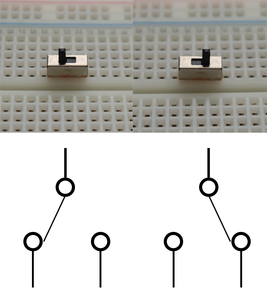
You don’t always have use an SPDT switch to choose between two options. It can be used just like any regular on-off switch by leaving one of the pins disconnected, or floating. This breaks the circuit path and prevents any current from flowing, like a simple power switch.
Note: Floating pins are open to the outside world and are not connected to any other part of the circuit. They can be affected by discharges of static electricity from the air or from contact with objects; for example, your fingers! These tiny discharges can cause voltage fluctuations at the pin, and any circuit that’s connected to them may mistakenly read HIGH or LOW pulses.
If an SPDT switch is being used for input, it is highly recommended to make sure all pins are connected to either a HIGH, LOW, or other circuit pin.
Building an Example Circuit
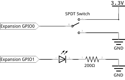
The first circuit we build will have the LED directly controlled by the switch to demonstrate how the switch works. The Omega will be used only as a power source and will not control the operation of the circuit.
What You’ll Need
Prepare the following components from your kit:
- 1x Omega plugged into Expansion Dock
- 1x Breadboard
- 1x SPDT switch
- 1x 200Ω Resistor
- 4x Jumper wires (M-M)
- 1x Any LED color of your choice!
Hooking up the Components
- Plug in the switch vertically across three rows.
- Connect the LED’s anode to the switch’s middle pin, and the cathode to an empty row.
- Connect one end of a 200Ω resistor to the LED’s cathode, and the other end into one of the “-” rails.
- We’ll call this the ground rail.
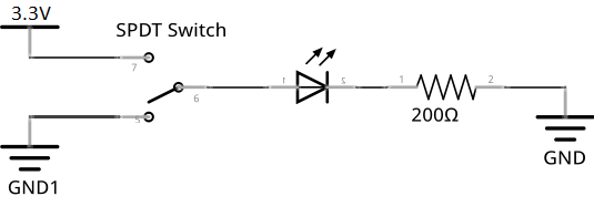
- Connect the Expansion Dock’s
GNDpin to the ground rail. - Connect the Expansion Dock’s ‘3.3V’ pin to the switch’s top pin.
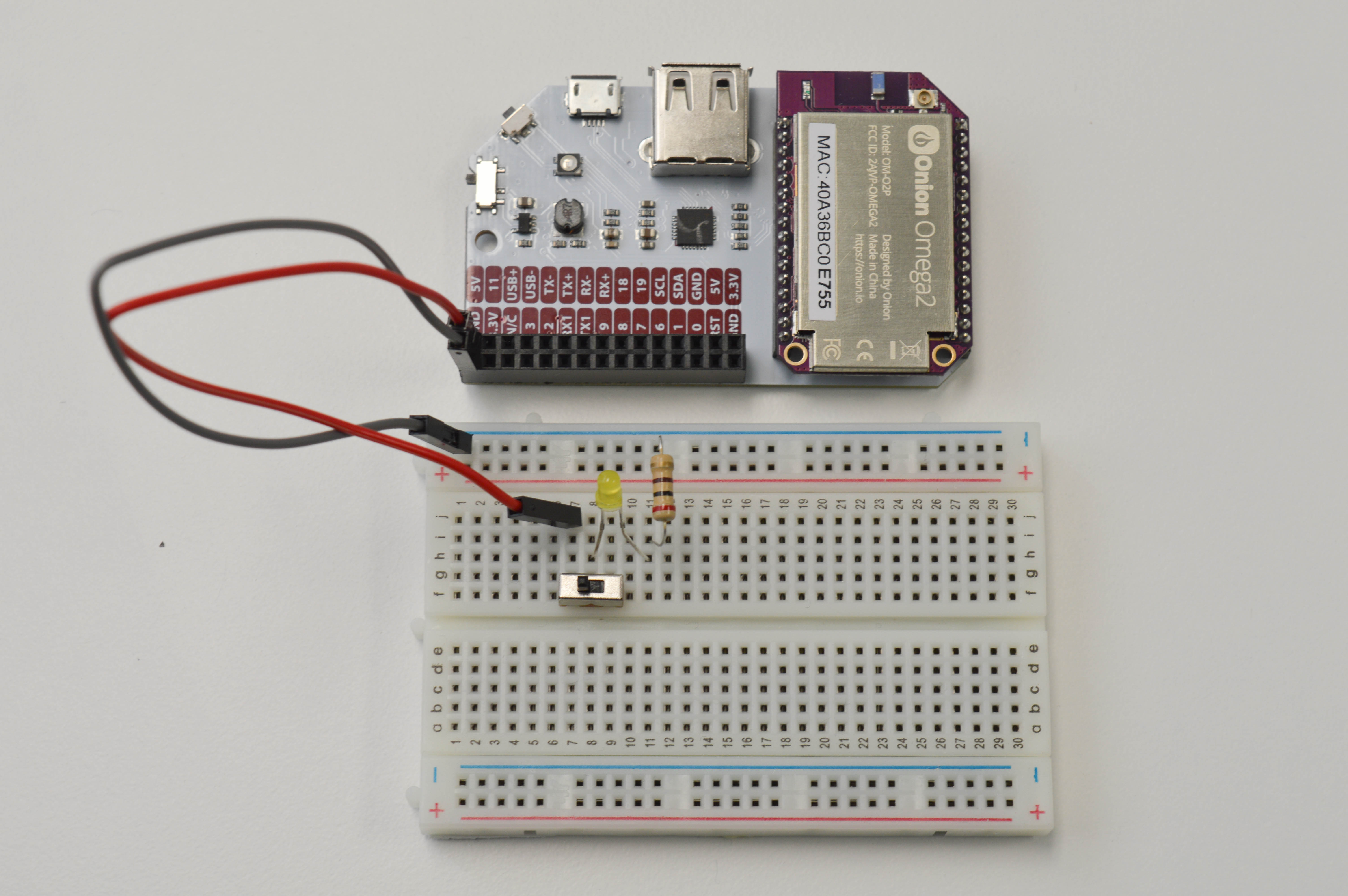
Your circuit should look like something like this:
Wiring Precautions
You may have noticed that we wired up all of the breadboard components and GPIO connections first before connecting the main power line. We do this to minimize the risk of making wiring mistakes and powering a circuit that could potentially damage the components or the Omega. This is good practice and we’ll be building circuits in this way throughout these experiments.
If you really want to make sure that your components are safe before performing an experiment, you can leave the Omega turned OFF before connecting power to the circuit. Once everything is connected, you can then turn the Omega on again.
What to Expect
The slide switch physically controls the electricity flowing to the LED.
- When the switch is set to the pull-up fork, the LED receives power and lights up.
- When the switch is set to the pull-down fork, the LED does not receive power and turns off.
This is circuit is quite direct - it demonstrates that this switch works and how it does so. In fact, the only reason we have the Omega connected is to supply power to the LED. Let’s move on to including our Omega and get some logic in this setup!
Building the Experiment Circuit
Now let’s try letting the Omega reading the signal the switch sends and use that to turn on the LED. We’ll rewire the circuit to have the Omega connecting the switch and the LED. Once we finished wiring the circuit, we’ll write a program that turns the LED on or off through reading the switch position.
What You’ll Need
- Use the same components as in the first circuit above.
- Throw in a few more jumper wires
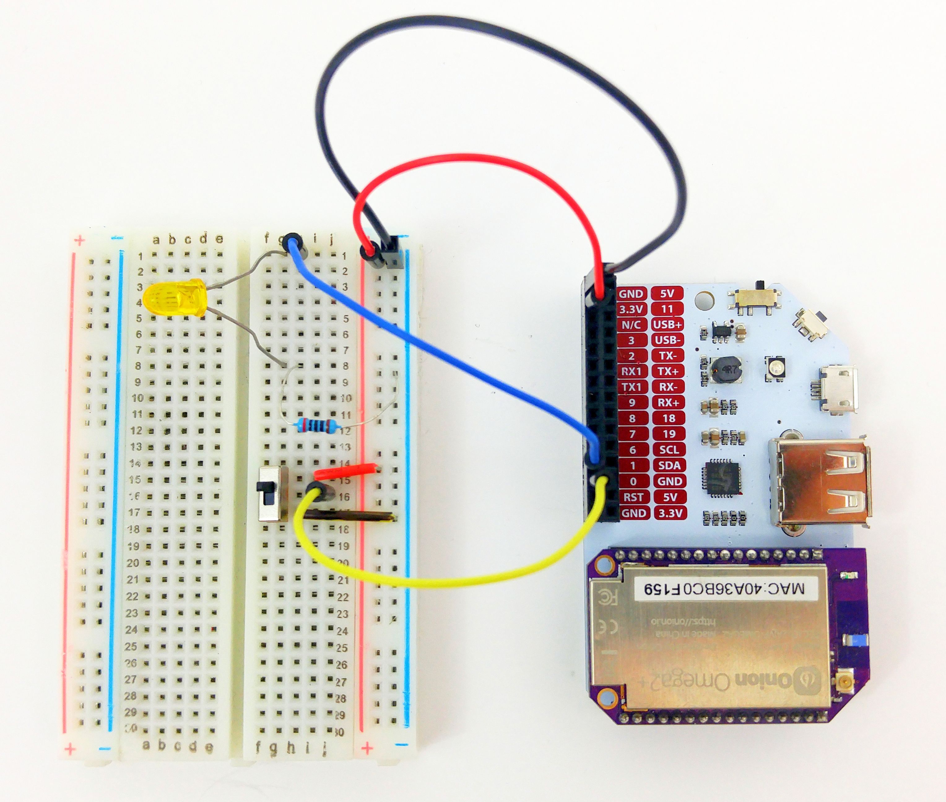
Hooking up the Components
This circuit will keep the switch, but route the output of the switch to the Omega instead, and have it control the LED through a GPIO.
- Remove the LED and resistor from the breadboard. Keep the switch and other wires in place.
- Connect
GPIO0on the Expansion Dock to the switch’s middle pin. - Connect the switch’s bottom pin to the ground rail.
- Place the LED back on the breadboard across two empty rows, then do the following:
- Connect the anode to
GPIO1using a jumper wire from the breadboard to the Expansion Dock. - Connect the cathode to one end of the 200Ω resistor.
- Connect the anode to
- Connect the other end of that resistor to ground.
Your circuit should look like this:
Writing the Code
Let’s make a new file called STK04-readSwitch.py to hold our code. This program will read in whatever state the switch is at, and then change the LED to match after some delay.
import onionGpio
import time

# specify sleep duration to be used in the program
sleepTime = 2

# set which GPIOs will be used
switchPin     = 0      # use GPIO0
ledPin        = 1      # use GPIO1


# instantiate GPIO objects
switch        = onionGpio.OnionGpio(switchPin)
led           = onionGpio.OnionGpio(ledPin)

# set the GPIO directions
switch.setInputDirection()               # switch pin is an input
led.setOutputDirection(0)                # led pin is an output

# infinite loop - runs main program code continuously
#   periodically check the switch and turn the LED on or off
while 1:
    # read the switch value
    switchValue = switch.getValue()
    # turn the LED on/off depending on the switch
    led.setValue(switchValue)

    # make the program pause
    time.sleep(sleepTime)
Let’s run the code:
python SKT04-readSwitch.pyNow try flipping the switch on and off. What happens?
What to Expect
This circuit works the same way as the first circuit, albeit with a much slower reaction to the switch input. This demonstrates a physical input affecting something virtual (like our script); the virtual entity can interpret the signal then proceed to act on the physical world or interact with other virtual entities.
A Closer Look at the Code
In this experiment, we continuously and repeatedly check the value of a sensor (our switch) then update the signal sent to the LED. This repeated checking is a classic way of reading a device and is called polling.
Polling
Polling is the process of repeatedly checking an input.
When flipping the switch, you may have noticed a delay of 2 seconds before the LED reacted. This delay was added so that the CPU has some time to rest between every check on the LED. Every time the program checks the switch, it puts a small load on the CPU - remember that it runs really fast, and doing many checks very often will waste CPU power that could be used for other system processes!
The delay length is set by the time.sleep(sleepTime) line. Try changing the sleepTime variable at the top to something shorter, like 0.5 or 0.1, and seeing what happens.
Polling is not without its issues:
- You can’t do anything else in the program.
- You need to find a polling speed that balances the time delay and stress on the CPU.
If only there were a better way of doing this!
Next we’ll learn how to use a shift register.