Controlling a 7-Segment Display
We’ve just learned a lot about shift registers. Now, let’s apply that knowledge to control a 7-segment Display so we can display numbers (and a few letters) in the physical world. We’ll connect the 7-segment display to the shift register that we wired up last time. We’ll write a program to send serial signals to the shift register which will be transformed into numbers and letters on the 7-segment display. We’ll then observe the output and see if there’s anything interesting we notice.
Note: This experiment builds on the previous one, so you should make sure you complete it before moving on!
7-Segment Display
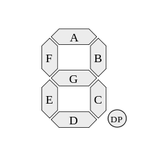
If you’re wondering why it’s called a 7-segment display, wonder no more!
If you take a look at a 7-segment display closely you’ll see that each digit is split into seven different segments, each lit up by an LED. Each segment is connected directly to an input pin and is controlled individually. See the diagram below for a typical labelling scheme:
7-segment displays with more than one digit usually have each segment connected in parallel across all of the digits; this is to save pins on the display module itself. For example, if you try to light up the segments will display a “1”, it will appear on all of the digits at the same time!
This isn’t really useful, so each digit has its own scan pin that groups segments for each digit together. This pin then controls whether the digit’s LEDs can be turned on or not.
To control the segments on a single-digit 7-seg display, you need at least seven GPIOs. And in order to control multiple digits at once, we need one additional GPIO for each scan pin. This can really add up, so we can use a shift register to increase the number of output pins available to us. This is usually how 7-segs are incorporated into a project in order to minimize the number of pins used on the controller.
7-segment displays are sometimes called “7-segs” for short.
Building the Circuit
The 7-segment display has an LED for each of the seven segments and an LED for the decimal point. That means there are 32 LEDs in total since there are four digits on the display.
The Omega by itself doesn’t have enough GPIOs to control all those LEDs, but we can make up for this by using the shift register in combination with only a handful more GPIOs!
Our general plan will look like this:

What You’ll Need
- 1x Omega2 plugged into Expansion Dock
- 1x 7-Segment Display
- 1x Shift Register
- 4x 330Ω Resistors
- Jumpers
- 12x M-F
- 13x M-M
Hooking up the Components
First things first, we’ll be building on our previous experiment.
- If you’ve done the previous experiment, keep the shift register connected to the Omega just like you had it. However, you’ll need to remove the LEDs and resistors.
- If you skipped it, we strongly recommend you check it out before moving on to this one!
It’s important that all components have a common ground connection. Signals are measured as the difference in voltage between the signal pin and ground, so all of the components need to be measuring from the same baseline.
Connecting your Shift Register
- Make sure the little “indent” on the chip is pointing towards the top of the breadboard.
- Plug in the chip at the top of the breadboard across the gap so that the pins sit in rows 1 through 8.
- Connect
Vcc(pin 16) andSRCLR(pin 10) to the+(Vcc) rail. - Connect
GND(pin 8) andOE(pin 13) to the-(ground) rail.
When you have the shift register wired up, it’s time to connect it to the 7-segment display. First, we’ll have to add current-limiting resistors since the display is a set of multiple LEDs. We recommend you set up the resistors across the center first, and do all the wiring in one go.
Connecting the 7-Segment Display
We’ve included a diagram below for reference instead of instructions, as this one has a lot of wiring to do and they end up going every which way. Note that all ends connecting to the 7-segment display require F jumper heads - that’s where your M-F jumpers will be used.
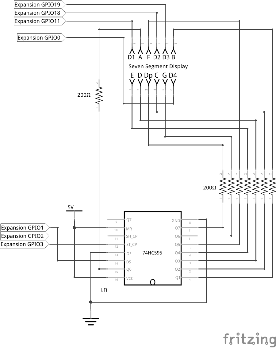
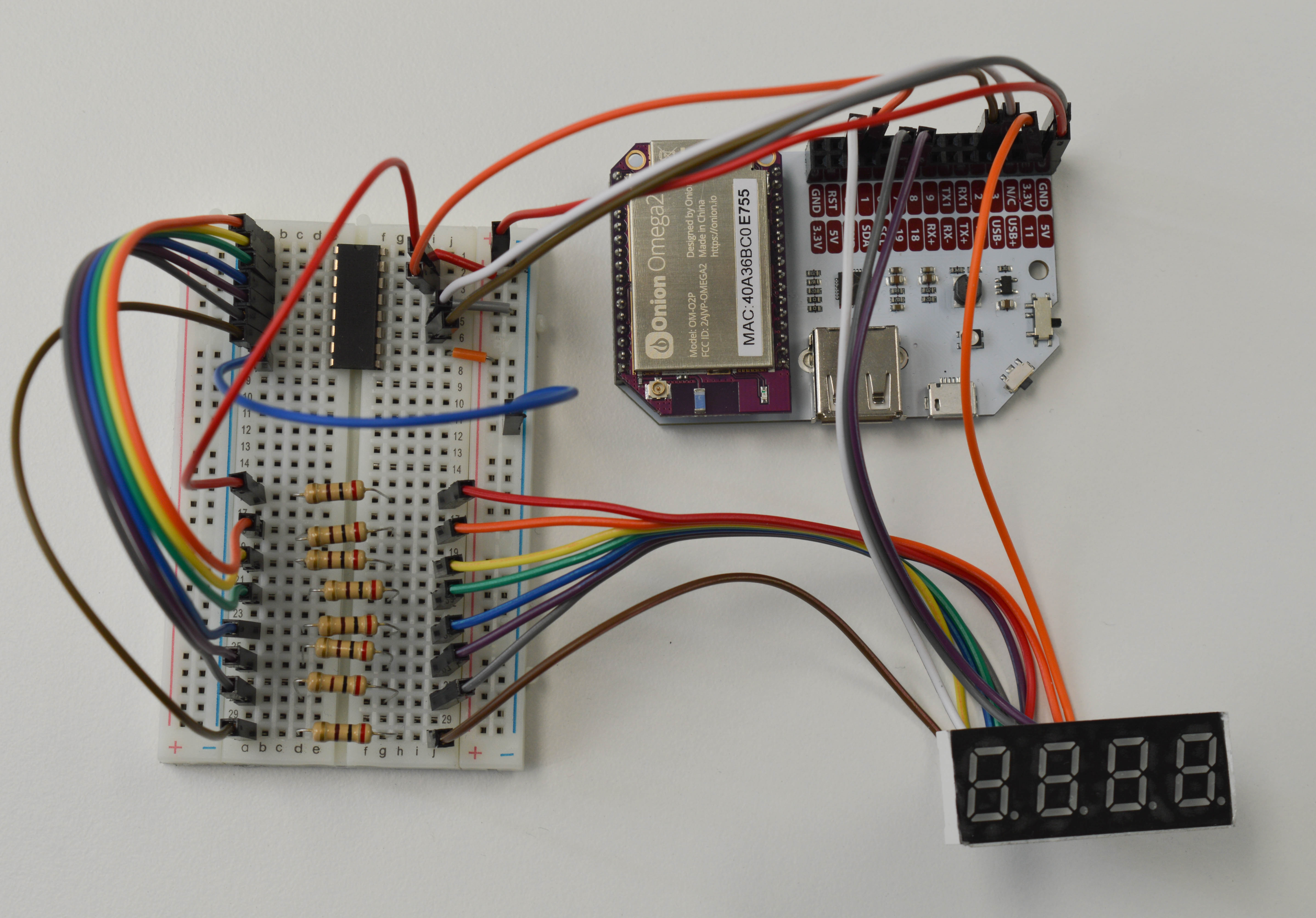
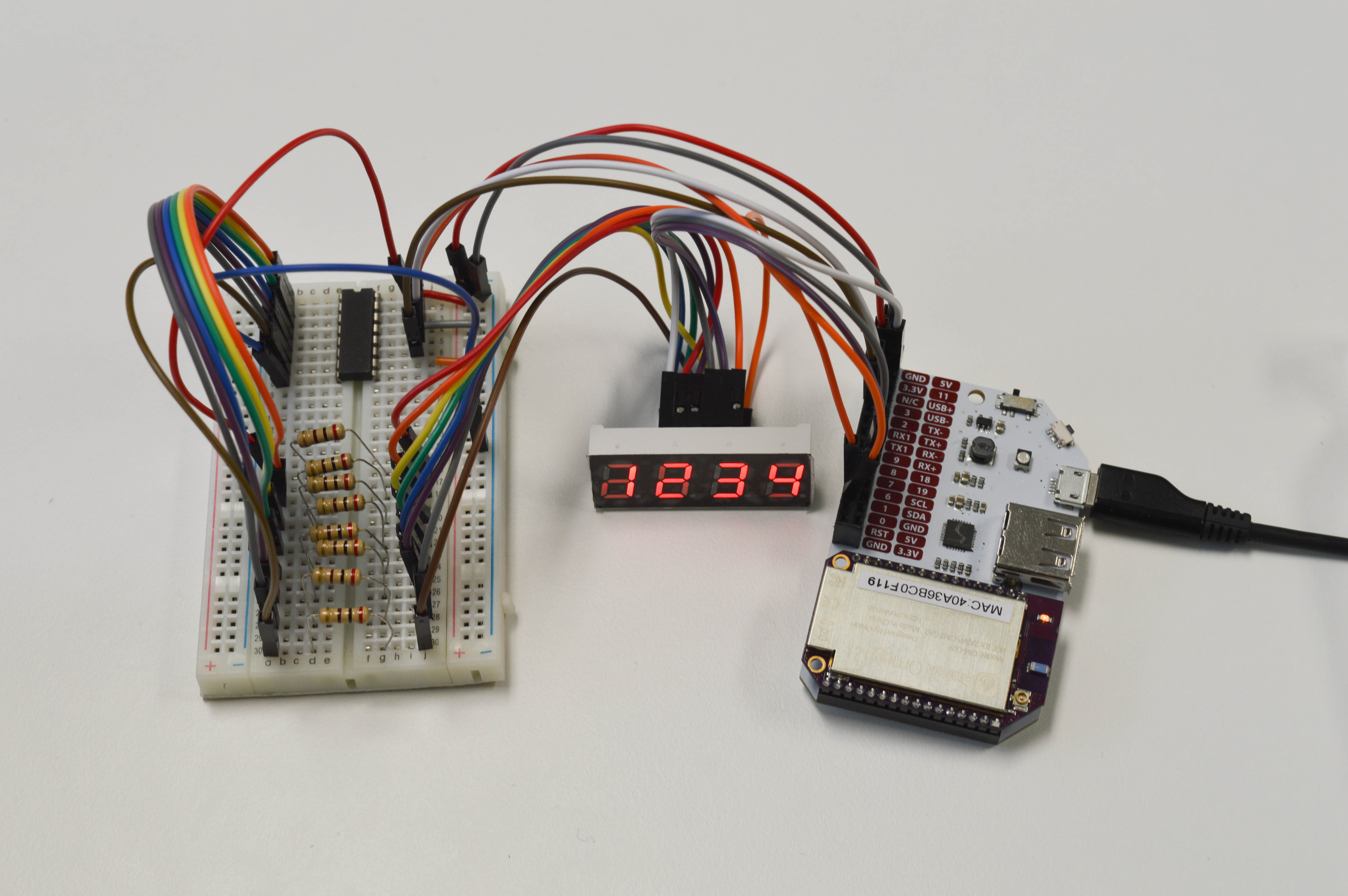
Once you’ve connected the 7-segment display to the Omega and shift register, you’re all done! Your circuit should look like this:
Wiring Precautions
You may have noticed that we wired up all of the breadboard components and GPIO connections first before connecting the main power line. We do this to minimize the risk of making wiring mistakes and powering a circuit that could potentially damage the components or the Omega. This is good practice and we’ll be building circuits in this way throughout these experiments.
If you really want to make sure that your components are safe before performing an experiment, you can leave the Omega turned OFF before connecting power to the circuit. Once everything is connected, you can then turn the Omega on again.
Writing the Code
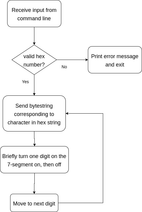
We’ll be developing a program that takes input from command line arguments when it’s launched and displays them on the 7-segment display. The basic flow will look like this:
To accomplish this, we will write a new class that uses and builds upon the shift register class from the previous experiment.
Now let’s create a class named sevenSegDisplay.py.
import registerClass
import onionGpio
import time

# class to control a 7-segment display
class SevenSegment:
    # class attribute
    # dictionary mapping each alphanumeric character to the bytestring that should be sent to the shift register
    digitMap = {
        "0": "11111100",
        "1": "01100000",
        "2": "11011010",
        "3": "11110010",
        "4": "01100110",
        "5": "10110110",
        "6": "10111110",
        "7": "11100000",
        "8": "11111110",
        "9": "11110110",
        "a": "11101110",
        "b": "00111110",
        "c": "10011100",
        "d": "01111010",
        "e": "10011110",
        "f": "10001110",
        "off": "00000000",
        "-": "00000010"
    }

    # instantiate the GPIO objects based on the pin numbers
    def __init__(self, pinList):
        # instantiate a shift register object
        self.shiftReg = registerClass.shiftRegister(1,2,3)
        self.digitPin = []

        # populate the digitPin list
        for i in range (0,4):
            # instantiate a GPIO object based on the current pinList element, and then add it to the digitPin list
            self.digitPin.append(onionGpio.OnionGpio(pinList[i]))
            # set the GPIO object to the output direction
            self.digitPin[i].setOutputDirection(1)

    # function to display a single digit
    # loop through this function repeatedly to display a multi-digit number
    def showDigit(self, d, character):
        self.digitPin[d-1].setValue(0)
        # write the bytestring that corresponds to the character we want to display
        self.shiftReg.outputBits(SevenSegment.digitMap[character])
        self.digitPin[d-1].setValue(1)

    # clear the seven segment and turn all LEDs off
    def clear(self):
        self.shiftReg.clear();
        for i in range (0,4):
            self.digitPin[i] = onionGpio.OnionGpio(dPin[i])
Now that we have a class to control the 7-seg display, let’s write our main script! Create a file called STK07-seven-seg-display.py and paste the following in it:
import registerClass
from sevenSegDisplay import SevenSegment
import time
import sys

# instantiate 7-segment object
sevenDisplay = SevenSegment([11,18,19,0])

# dictionary of error messages
errorMsgs = {
    "missingArguments": "Please input a hex number, eg. 0x12ab",
    "tooManyArguments": "Too many arguments. Please input only one hex number.",
    "tooShort": "Hex number is too short. Please include 4 digits after the 0x.",
    "tooLong": "Hex number is too long. Please include only 4 digits after the 0x.",
    "notHexNumber": "Input string is not a valid hex number. "
}

def __main__():
    # if script was called with no arguments
    if len(sys.argv) == 1:
        print errorMsgs["missingArguments"]
        return -1

    # if script was called with too many arguments
    elif len(sys.argv) > 2:
        print errorMsgs["tooManyArguments"]
        return -1

    # read the hex string from the argument
    # extract the digits following the 0x
    # convert any uppercase letters to lowercase
    inputHexString = sys.argv[1]
    inputHexString = inputHexString.split("x")[1]
    inputHexString = inputHexString.lower()
    inputLen = len(inputHexString)

    # validate the string's length
    if inputLen < 4:
        print errorMsgs["tooShort"]
        return -1
    elif inputLen > 4:
        print errorMsgs["tooLong"]
        return -1

    # check if valid hex digits (09, a-f)
    try:
        int(inputHexString, 16)
    except ValueError:
        print errorMsgs["notHexNumber"]
        return -1

    # attempt to display out the hex string
    while True:
        for i in range(inputLen):
            sevenDisplay.showDigit(i,inputHexString[i])

# for running from the command line
if __name__ == '__main__':
    __main__()
The for loop here is doing something really neat with only one line of code:
- The
showDigit()function is called with a digit numberiand digit characterinputHexString[i]to be displayed. - In this function, the scan pin for the current digit is enabled and is ready to light up.
- We then send to the shift register the binary values corresponding to the segments for the current digit.
We then cycle through all of the digits and repeat the steps above for each one.
Let’s choose a hexadecimal number to display on the 7-seg. Come up with a string that looks like this: 0x12ab, where the four digits 12ab can be any number from 0 to 9 OR a letter from A to F. Then run the following command in the terminal, replacing YOURHEXNUMBERHERE with your string:
This numbering system is known as hexadecimal or base 16, where each digit can have a value from 0 - 15; the numbers 10 to 15 are represented by the letters A to F respectively. This is different from our everyday decimal (base 10) system where each digit can have a value from 0-9. Hexadecimal (“hex” for short) is very useful in expressing binary numbers with few digits. For example, the eight-digit binary number 0b11000000 (192 in decimal) can be expressed in two digits in hex as 0xC0!
Freeing Up GPIOs
If you try to run the script and experience an error that looks like this:
IOError: [Errno 16] Resource busythen you may have to free the GPIOs for use back into the filesystem. Create a file called freeShiftRegGpios.sh and paste the following in it:
echo 1 >/sys/class/gpio/unexport
echo 2 >/sys/class/gpio/unexport
echo 3 >/sys/class/gpio/unexport

echo 11 >/sys/class/gpio/unexport
echo 18 >/sys/class/gpio/unexport
echo 19 >/sys/class/gpio/unexport
echo 0 >/sys/class/gpio/unexport
This unexports the GPIOs, making them available for use by other programs.
What to Expect
If run correctly, the code above should print the digits one by one on the 7-segment display. If the hex number was not entered in correctly, it will print an error message and exit.
The code runs in an infinite loop which you can exit with Ctrl-C (Cmd-C for Mac users).
Wow, what’s up with that?
You may be wondering if this is normal - the answer is yes. The digits on the 7-seg will be turning on and off in order slowly enough for you to notice. However, you probably guessed that it really should be displaying them all at once.
A Closer Look at the Code
This code couldn’t exactly do what we needed it to, but there are still some important concepts shown here.
To display numbers on the 7-seg, we mapped the characters to binary bytestrings using a dictionary. We also included a class within another class to better abstract the operation of the physical components.
However, the end result was limited by the software we used: we wanted and expected the 7-segment display to light up all at once, but our script couldn’t make it happen fast enough. This is because the underlying onionGpio class is written so that it accesses the filesystem multiple times for each GPIO write, and the Omega cannot run these commands fast enough.
Software Limitations
In this experiment, the software and hardware interact to produce behaviour we didn’t intend. The code runs as well as it possibly can, and the hardware does its best to operate from the signals its given, but ultimately the result is not workable. The root cause is the way the onionGpio library is programmed.
The GPIOs are operated by reading and writing to files. Every time we call onionGpio.setValue() on a GPIO, the library does the following:
- Takes control of or “exports” the GPIO in the filesystem
- Sets the GPIO’s direction to output
- Sets the GPIO’s output value
- Releases or “unexports” the GPIO for future use
The onionGpio module does this in a very safe and consistent way via our C library. However, this also means that it’s quite slow and not fast enough for our display.
Classes using Classes
You’ll notice that we declare an object of the ShiftRegister class within the SevenSegment class. This is a good example of the following concepts:
- Code reusability: Earlier we wrote an independent class for the shift register, but now we’re using it like a Lego block to build something new. This lets us focus on new code for the 7-seg. We can do this for any other device that requires a shift register without writing another copy of the class.
- Abstraction: The
ShiftRegisterclass gives us full control over a shift register device. However, when we’re working with a 7-seg, we don’t really care about the shift register anymore. At most, we should only have to tell theShiftRegisterobject which GPIOs to use and it would take care of the rest; we can then work on translating text input into which LED segments to light up.
These ideas makes it easier to think about how different pieces of a project work together. This helps us focus on designing systems and logic rather than getting bogged down in the details.
Dictionary
So far we’ve been working with lists, which are collections of one or more data values in order. The values in lists are indexed by numbers, for example students[3]. However, there are times when we’re more interested in working with these values by using meaningful names than working with them in order. Enter the dictionary!
Dictionaries are data structures that contain key-value pairs. A key is a name or label, and the value is some data that you want to associate with that key; it could even be another dictionary! Dictionaries are indexed by their keys, for example students["Robert Tables"].
Let’s look at the digitMap dictionary used to store the bytestrings for each character in the SevenSegment class:
Instead of creating individual variables for each and every character, we can use the dictionary to act as a translator between characters and the values that need to be written to the shift register. if we wanted to display the character 1, we send the required bytestring to the shift register by calling digitMap["1"] instead of typing 00000110; the same goes for any other character.
We can use this to keep our code neat and short. By using the values of other variables as keys, we can turn this:
if character == "a":
    shiftReg.outputBits("01110111")
elif character == "b":
    shiftReg.outputBits("01111100")
# and so on
Into this:
In Python, dictionary keys can be strings, integers, or tuples. In the digitMap dictionary, we use strings to make it easy to work with other functions that send strings, for example from command line arguments in our main script.
Dictionaries work similarly in programming as they do in real life: You can find a definition (value) by looking up a name or title (key). Dictionaries are also mutable, meaning that you can add new key-value pairs, or modify existing ones!
Dictionaries have similar concepts in other programming languages, such as Objects in JavaScript and structs in C.
A Better Way?
Our Python implementation couldn’t perform as fast as we needed it due to how the onionGpio library performs multiple file writes when working with the GPIOs. However, we have another tool up our sleeve: ash!
ash, or the Almquist Shell, is a lightweight Unix shell. One of its variants, BusyBox ash, is included in the Omega’s firmware and can be run by calling sh. This tool is used for running shell scripts, which are collections of terminal commands structured like a program.
We’ve changed how we’re going to be accessing and controlling the GPIOs by working with the filesystem directly. If you’d like to see how that looks, we’ve provided a shell script below that does this properly.
Create a file called STK07-ash-seven-segment-display.sh and paste the following in it:
#!/bin/sh

# read the command line argument
input=$1
# get the length of the input string
len=${#input}

# parse each character from the input string into its own variable
pref1="$(echo $input | sed -e 's/^\(.\).*/\1/')"
pref2="$(echo $input | sed -e 's/^.\(.\).*/\1/')"
chr1="$(echo $input | sed -e 's/^..\(.\).*/\1/')"
chr2="$(echo $input | sed -e 's/^...\(.\).*/\1/')"
chr3="$(echo $input | sed -e 's/^....\(.\).*/\1/')"
chr4="$(echo $input | sed -e 's/^.....\(.\).*/\1/')"

# check if the input string is formatted correctly
if  [[ "$len" -ge "7" || "$pref1" != "0" || "$pref2" != "x" ]]; then
    echo "Please input a hex number in the following format: 0x12ab"
    exit
fi

# digit mapping
#   there is no dictionary-type data structure in ash, so must write these by hand :()
mapDigit(){
    if [ "$1" == "0" ]; then
        echo "1 1 1 1 1 1 0 0"
    elif [ "$1" == "1" ]; then
        echo "0 1 1 0 0 0 0 0"
    elif [ "$1" == "2" ]; then
        echo "1 1 0 1 1 0 1 0"
    elif [ "$1" == "3" ]; then
        echo "1 1 1 1 0 0 1 0"
    elif [ "$1" == "4" ]; then
        echo "0 1 1 0 0 1 1 0"
    elif [ "$1" == "5" ]; then
        echo "1 0 1 1 0 1 1 0"
    elif [ "$1" == "6" ]; then
        echo "1 0 1 1 1 1 1 0"
    elif [ "$1" == "7" ]; then
        echo "1 1 1 0 0 0 0 0"
    elif [ "$1" == "8" ]; then
        echo "1 1 1 1 1 1 1 0"
    elif [ "$1" == "9" ]; then
        echo "1 1 1 1 0 1 1 0"
    elif [[ "$1" == "a" || "$1" == "A" ]]; then
        echo "1 1 1 0 1 1 1 0"
    elif [[ "$1" == "b" || "$1" == "B" ]]; then
        echo "0 0 1 1 1 1 1 0"
    elif [[ "$1" == "c" || "$1" == "C" ]]; then
        echo "1 0 0 1 1 1 0 0"
    elif [[ "$1" == "d" || "$1" == "D" ]]; then
        echo "0 1 1 1 1 0 1 0"
    elif [[ "$1" == "e" || "$1" == "E" ]]; then
        echo "1 0 0 1 1 1 1 0"
    elif [[ "$1" == "f" || "$1" == "F" ]]; then
        echo "1 0 0 0 1 1 1 0"
    else
        echo "Invalid hex digit $1."
        exit
    fi
}

# map the digits in the input string to their bytestrings
dig1=$(mapDigit $chr1)
dig2=$(mapDigit $chr2)
dig3=$(mapDigit $chr3)
dig4=$(mapDigit $chr4)

# setup shift register pins
echo 1 >/sys/class/gpio/export # data
echo 2 >/sys/class/gpio/export # clock
echo 3 >/sys/class/gpio/export # latch

# setup digit pins
# all directions are from left
echo 11 >/sys/class/gpio/export # digit 1
echo 18 >/sys/class/gpio/export # digit 2
echo 19 >/sys/class/gpio/export # digit 3
echo 0 >/sys/class/gpio/export # digit 4

# set direction for the pins above (out/input)
echo out >/sys/class/gpio/gpio1/direction
echo out >/sys/class/gpio/gpio2/direction
echo out >/sys/class/gpio/gpio3/direction

echo out >/sys/class/gpio/gpio11/direction
echo out >/sys/class/gpio/gpio18/direction
echo out >/sys/class/gpio/gpio19/direction
echo out >/sys/class/gpio/gpio0/direction

# function to write out values from the SR's buffer to the outputs
latchSR (){
    echo 1 >/sys/class/gpio/gpio3/value
    echo 0 >/sys/class/gpio/gpio3/value
}

# function to pulse the SR clock and shift in one bit from the data line
pulseClock (){
    echo 1 >/sys/class/gpio/gpio2/value
    echo 0 >/sys/class/gpio/gpio2/value
}

# function to set one digit
setOneDig(){

    echo out >/sys/class/gpio/gpio1/direction

    for i in $8 $7 $6 $5 $4 $3 $2 $1
    do
        #echo
        echo $i >/sys/class/gpio/gpio1/value
        pulseClock
    done

    latchSR
}

# function to turn off all the pins (enable pins are active LOW)
initDigPins (){
    echo 1 >/sys/class/gpio/gpio0/value
    echo 1 >/sys/class/gpio/gpio18/value
    echo 1 >/sys/class/gpio/gpio19/value
    echo 1 >/sys/class/gpio/gpio11/value
}

# initialize the digit pins
initDigPins

# loop forever
while true; do

    # turn one digit on and write to the shift register
    echo 0 >/sys/class/gpio/gpio0/value
    setOneDig $dig3
    # then turn it off and prepare to switch to the next digit
    echo 1 >/sys/class/gpio/gpio0/value

    # enable the digit
    echo 0 >/sys/class/gpio/gpio19/value
    setOneDig $dig1
    echo 1 >/sys/class/gpio/gpio19/value

    echo 0 >/sys/class/gpio/gpio11/value
    setOneDig $dig2
    echo 1 >/sys/class/gpio/gpio11/value

    echo 0 >/sys/class/gpio/gpio18/value
    setOneDig $dig4
    echo 1 >/sys/class/gpio/gpio18/value
done
Now run this script in the same way as the Python script before, except replace python with sh:
sh /root/STK07-ash-seven-seg-display.sh YOURHEXNUMBERHEREWhat to Expect
You should now see the characters display without flickering, much better than last time!
A Closer Look at the Shell Script
This shell script looks a lot different from our Python code! The biggest difference is that there are no lists nor dictionaries in ash, and that we only export the GPIOs once.
No Lists Nor Dictionaries
In our Python script, we were able to access each individual character of the input hex string by simply treating the string as a list and iterating over each character, as in inputHexString[i]. However, ash doesn’t support lists and so we have to load each character into its own variable, chr1 to chr4. This is done using the sed command; for a full reference of this powerful tool, check out this online tutorial.
The same goes for our digit map. Since we can’t simply call digitMap[character], we wrote a function mapDigit() that takes a character as an argument and returns the corresponding bytestring if found.
Exporting the GPIOs Once
Since we know that the GPIOs are all supposed to be outputs only, we can export them only once at the beginning and not have to worry about freeing them up for other purposes later.
The rest of the script is similar to the Python implementation where we repeatedly change the scan pin and send different values to the shift register. This is faster because we only now have to access the filesystem once to set the GPIOs each time!
Writing this type of code requires a deeper understanding of how the hardware and software interact. If you’re curious, you can take a look at some examples in our Developing Using the Command Line Guide.