Blinking an LED
In our very first experiment, we’re going to blink an LED on and off. This is the hardware development equivalent of the ‘Hello World’ program. This first experiment will start small but it will be a solid foundation for the rest of the experiments.
Remember, when inventing and building new things, try to break the work down into bite sized chunks, that way you’ll see progress much sooner and it will motivate you to keep going!
GPIOs as Outputs
The Omega has fifteen General Purpose Input/Output pins (commonly referred to as GPIOs) that can be fully controlled by you, the user. For now, let’s focus on using GPIOs in the output direction.
Once a GPIO is set to the output direction, you can have it output either a logical LOW or a logical HIGH. The exact voltage of each will depend on the system that’s being used; on the Omega, logical LOW is 0V and logical HIGH is about 3.3V.
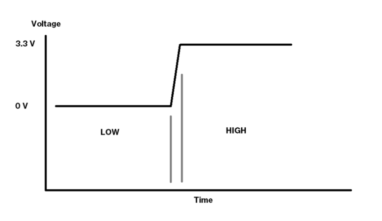
These logical HIGH and LOW signals can be used to control external circuits that are separate from the Omega, and are the foundation for your digital circuits!
LEDs
Now let’s talk about Light Emitting Diodes, or as they’re more commonly known, LEDs. A regular diode is an electronic component that allows current to flow in only one direction. Think of it as a very strict policeman watching a one-way street. An LED is a type of diode that lights up when there is current flowing through it (but only when it’s flowing in the right direction)!
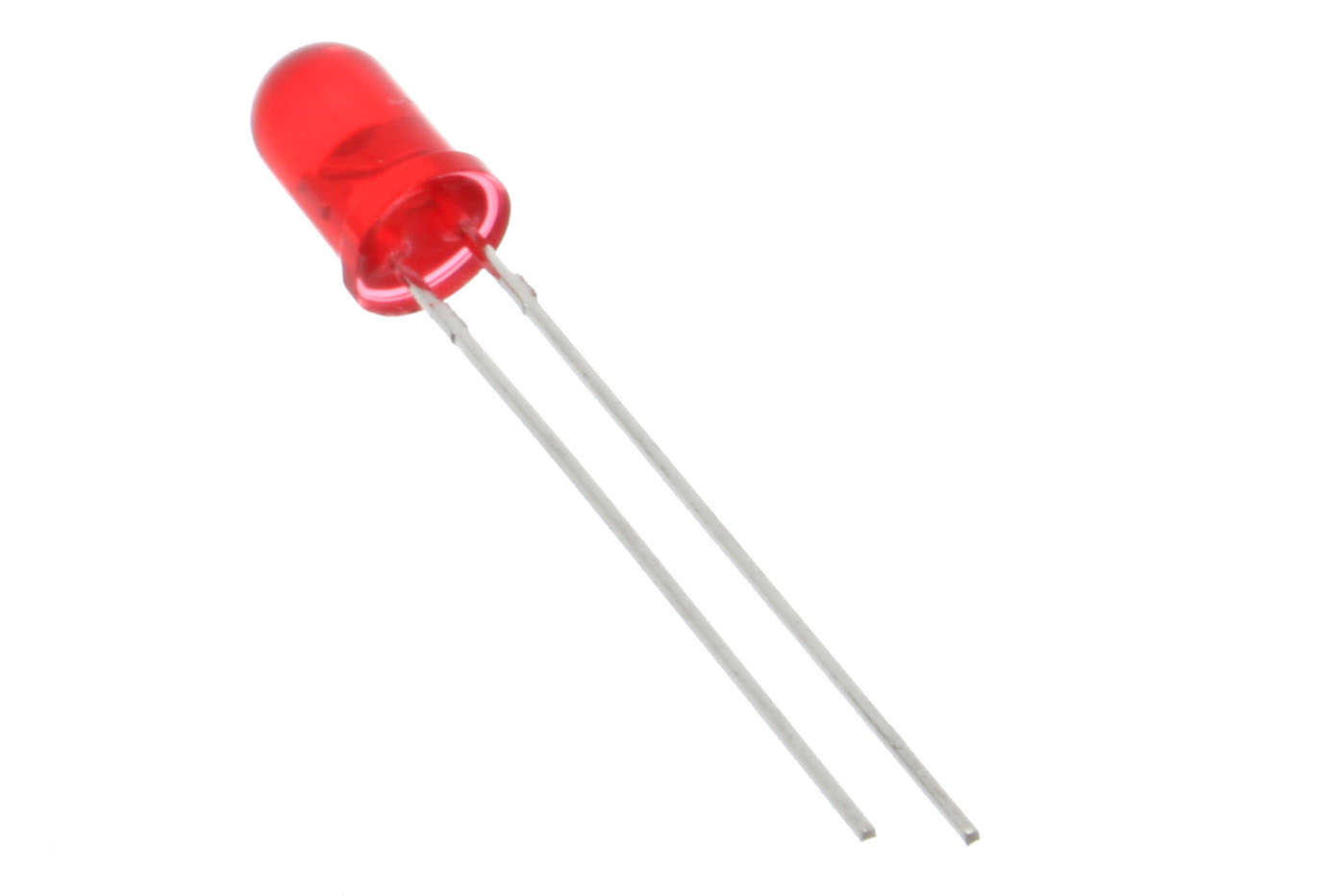
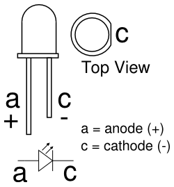
If you look closely, you’ll see that every LED has a longer leg and a shorter leg. This is because LEDs are diodes and we need to know in which direction it will allow current to flow.
- The longer leg is the positive side, called the anode. It should always be connected to the current source.
- The shorter leg is the negative side, called the cathode, where the current exits the LED. Always connect this side towards the ground connection.
Just like a regular light bulb, an LED can burn out if it’s supplied with too much current. LEDs in electronics are almost always used in series with a current limiting resistor that, you guessed it, will put a limit on how much current can pass through the LED.
For more information on how a resistor can limit current, we recommend checking out this Sparkfun tutorial on Ohm’s law
How to Build Circuits
Before we start building our experiment, let’s first go over some of the building blocks when it comes to experimenting with electronics.
Jumper Wires
We’ll be using jumper wires in all of our experiments and projects. They all work the same; connecting two points in a circuit together.
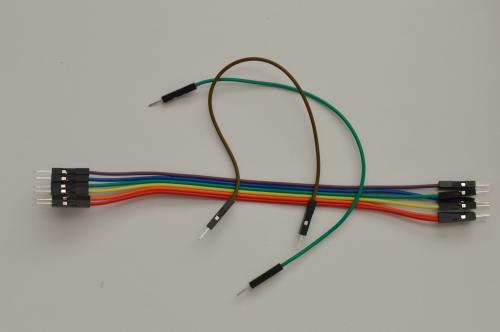
Jumper wires have ends that are either male or female. They both do the same thing, but the different ends make them work better in different situations.
Male ends are used to connect inputs and outputs that are enclosed in sockets - breadboards and the pins on the expansion docks are examples of where you’d need male jumper ends.
Female ends are able to connect to inputs and outputs that are true pins, for example on the PWM expansion, every wire that needs to be plugged into the PWM channels require a female end to work.
Depending on your needs, you can plug jumpers male to female to create longer jumpers, or to replace missing jumpers of a specific kind.
Breadboard
The breadboard is the foundation of all of the experiments we’re going to do together, and the starting-point for prototyping many electronics projects and even products!
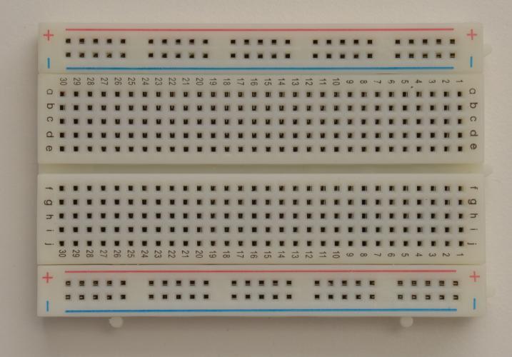
The breadboard’s sockets are connected to pieces of metal inside that are directly electrically connected (or “shorted”) to each other in a way to make it easy for you to build and prototype circuits.
The vertical columns labelled + and - that run along the sides of the breadboard are called the power rails. The sockets in each rail are shorted vertically. The + rail is commonly used for Vcc or power connections, and the - rail is typically used for ground.
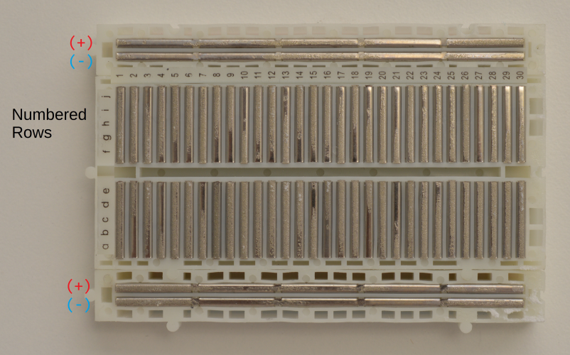
The sockets on the left and right side of the gap in the middle are called the terminal rows. In each row, the sockets marked a through e are shorted horizontally to each other, and same goes for the sockets f through j. When plugging integrating circuits (ICs) into the board, this lets you connect up to 4 wires per pin.
Building the Circuit
Now that we’ve gotten familiar with the tools we’ll be using, let’s build our very first circuit!
What You’ll Need
Prepare the following components from your kit:
- Omega plugged into Expansion Dock
- Breadboard
- M-M Jumper Wires
- 1x 200Ω Resistor
- Any LED color of your choice!
Hooking up the Components
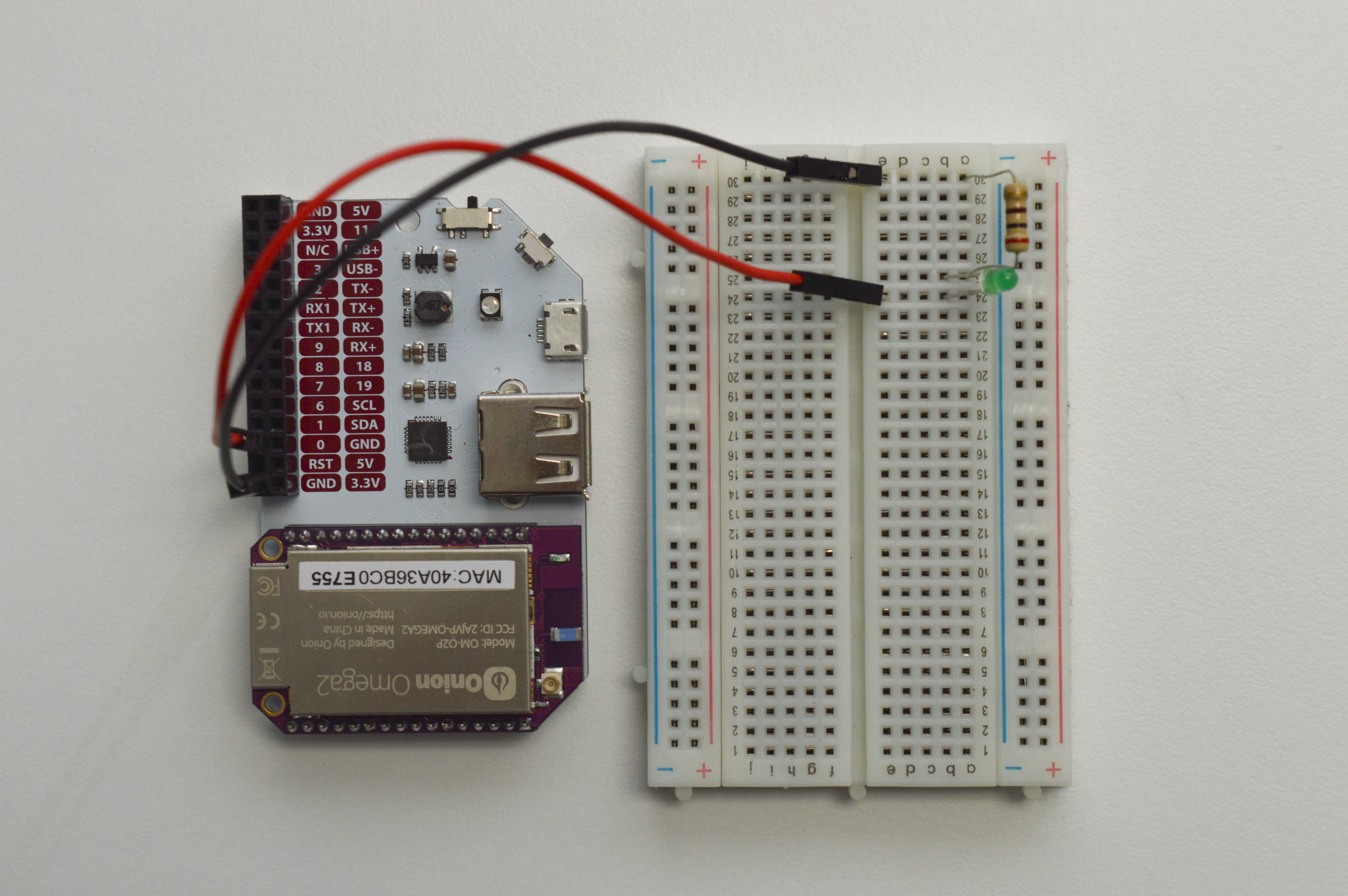
OK here we go, let’s put together our circuit! We’re going to be connecting an LED’s anode to a GPIO on the Omega2, and cathode to Ground through a current limiting resistor.
- Plug in the LED into the breadboard, make sure you plug the anode and cathode into different rows and that you know which is plugged where.
- Now connect one end of a 200Ω resistor to the the cathode row, and the other end to an empty row.
- Connect the other end of the resistor to a Ground pin on the Omega2.
- Let’s choose
GPIO0on the Omega2 to drive our LED, so connect a jumper wire fromGPIO0to the LED’s anode.
Your circuit should now look like this:
Wiring Precautions
You may have noticed that we wired up all of the breadboard components and GPIO connections first before connecting the main power line. We do this to minimize the risk of making wiring mistakes and powering a circuit that could potentially damage the components or the Omega. This is good practice and we’ll be building circuits in this way throughout these experiments.
If you really want to make sure that your components are safe before performing an experiment, you can leave the Omega turned OFF before connecting power to the circuit. Once everything is connected, you can then turn the Omega on again.
A note on components with and without polarity:
You’ll notice that we were careful to make sure which end of the LED we connected to incoming current and which we connected to ground. This is because LEDs are polarized, so they will only when current is flowing in the correct direction, that is, when they’re plugged in the correct way.
With the resistor, either way will work since resistors are symmetric components, meaning they don’t care which way current flows through them, they’ll work either way.
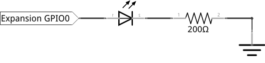
The circuit diagram for our first experiment looks like this:
Writing the Code
Now we get to write the code that will make our circuit actually do something! That something will be blinking our LED!
We’ll be writing code in the Python programming language. It is designed to be accessible to beginners while also being powerful enough to run major software programs, web services, research tools, and more.
Let’s make a new file called STK01-blink.py to hold our code:
import onionGpio
import time

# specify sleep duration to be used in the program
sleepTime = 0.5

# instantiate a GPIO object
gpio0 = onionGpio.OnionGpio(0)
# set to output direction with zero (LOW) being the default value
gpio0.setOutputDirection(0)

# create a variable to hold the value of the LED
ledValue     = 1

# infinite loop - runs main program code continuously
while 1:
    # set the GPIO's value
    gpio0.setValue(ledValue)

    # flip the value variable
    if ledValue == 1:
        ledValue = 0
    else:
        ledValue = 1

    # make the program pause
    time.sleep(sleepTime)
To run our Python program, enter the following in the Omega’s command line:
python STK01-blink.pyWe’ll be running our programs in this way in the following experiments.
What to Expect
Your LED should be blinking. It should turn on for half a second, and then turn off for half a second, repeating until you exit the program by pressing Ctrl-C.
To exit a program like this one: press
Ctrl-C(Cmd-Cfor Mac users)
A Closer Look at the Code
This is a small program, but there are quite a few things going on. Let’s take a closer look.
Importing a Module
The first line in the code imports a Python source code module. In this case, the module was made by us at Onion for controlling the Omega’s GPIOs. The module contains a class that implements functions for everything you can do with a GPIO on an Omega.
Object Oriented Programming - Instantiating an Object
Before we continue, we’d like to mention that Python is an Object Oriented programming language. This means we can make use of classes and objects.
In Object Oriented Programming, classes are blueprints or abstractions of code. An object is a copy of data and/or functions created from a class blueprint. In a program, you can create as many copies (objects) of a class whenever you need to!
For example, you can write a class for a “four sided shape” that contains data for length and width. You can then use it to create objects such as a “square” or a “rectangle”. Creating an object from a class is called instantiation, and objects created from a class are called instances.
We’ll explain these concepts in better detail as we go along in the following experiments.
Now back to our program! After we import the onionGpio module, we instantiate an OnionGpio object in this line:
Here we passed the number 0 as an argument to the constructor of the OnionGpio class. The constructor is a function that runs when an object is instantiated and can be used to supply data to the object that it could need for configuration. In our case, the OnionGpio constructor tells the object which of the Omega’s GPIOs the object will use, in this case GPIO0. We assign this instantiated object to a variable gpio0 so that we can use it later in the program to interact with the GPIO pin.
The time Module
This module is used for anything involving measuring time, but also contains the very important sleep() function. This function, pauses execution of the Python script for the specified time in seconds; similar functions in other languages may interpret the number as milliseconds. It can accept decimal numbers too!
While Loop
Loops are structures used to control program flow by repeating certain sections of the code multiple times. They are a very common and important building block in programming.
Here we’re using a while loop: the code inside the loop will run over and over while a given condition holds true. In this case, the loop condition is 1, which is equivalent to True in these situations, so we have in effect made an infinite loop.
Before program enters the loop, we set the ledValue variable to 1. Inside the while loop, we assign the value of ledValue (1) to our LED GPIO which turns it on. Then we reverse the value using the if-else statement which looks at the latest value of ledValue: if it is 1, it will be changed to 0 and vice versa. The program will then pause the program execution for half a second, at the time.sleep(sleepTime) statement.
The program then returns back to the beginning of the loop and assigns the new value of ledValue to the GPIO, and repeats the steps we described in the paragraph paragraph until you exit the program (Ctrl-C).
If you’re wondering why we make the program sleep for half a second every loop cycle, it’s because computers execute program code really fast. Try increasing, decreasing, or getting rid of the sleep instruction all-together and running the program again. See what happens with the LED.
Next we’ll learn how to blink multiple LEDs.