Isolated Control with the Relay Expansion
In this expriment, we’ll use a switch with the Omega Relay Expansion to turn a buzzer on or off. Along the way, we’ll be looking into why relays are useful, and go into more detail regarding pitfalls when interacting with hardware.
Circuit Isolation with Relays
The Omega is designed to handle around 3.3V and the Docks up to 5V. Attempting to directly control 120V appliances like lights, kettles, garage doors will almost certainly fry the Omega. So how can you automate these household appliances with an Omega?
Enter the Relay! A relay is a mechanical switch that is triggered electronically. This physically separates the circuit that switches and the circuit that the switch controls. The Relay Expansion is designed to isolate the Omega and the Dock (the switching circuit) from the controlled circuits. Turning lights on and off, opening the garage, and resetting wireless routers are all kinds of possible with the Relay.
The Relay Expansion
The Relay Expansion adds a plug-and-play relay to the Omega. It contains two relays that are controlled by the Omega - called channels 0 and 1. Each Relay Expansion can be assigned a three-bit address by toggling the address switches on the Expansion itself. This means a total of eight Relay Expansions can be uniquely identified by the Omega at the same time. This makes for a total of 16 possible independent relays that can be controlled at a time.
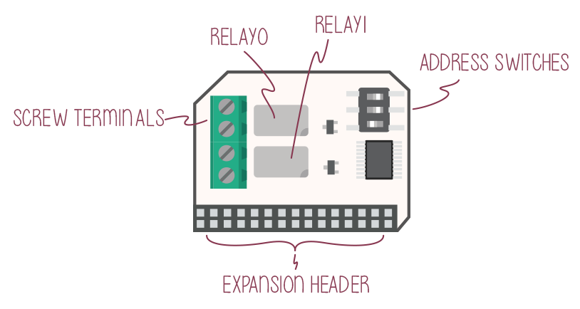
The Address switches
The address switch allows you to change the I2C address of the board. This is needed to differentiate multiple Relay Expansions from each other when connected to the same Omega.
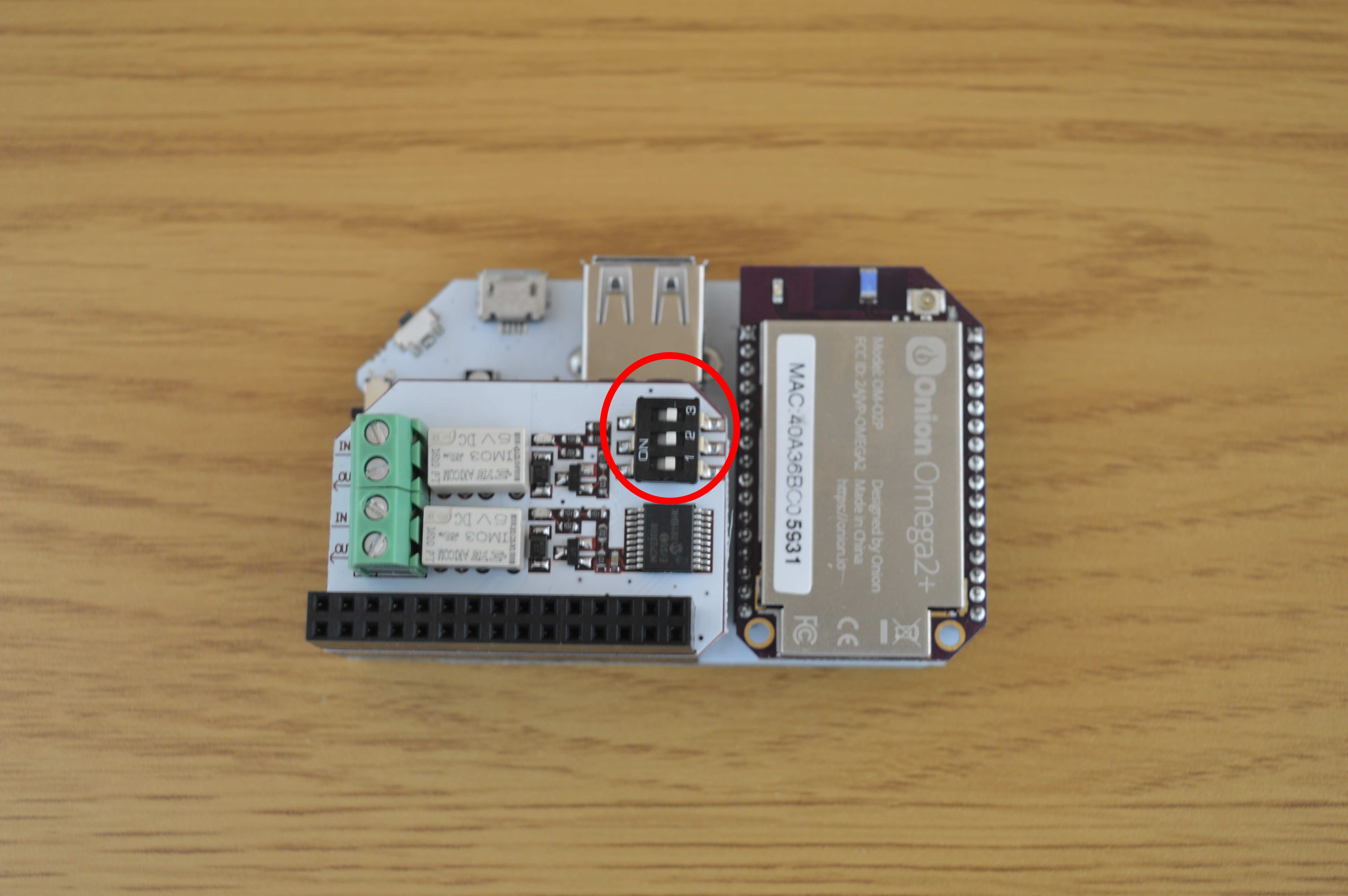
It has 3 switches that can be turned either ON or OFF. See the following table for the address values:
| Switch 1 | Switch 2 | Switch 3 | Binary Value |
|---|---|---|---|
| OFF | OFF | OFF | 000 |
| OFF | OFF | ON | 001 |
| OFF | ON | OFF | 010 |
| OFF | ON | ON | 011 |
| ON | OFF | OFF | 100 |
| ON | OFF | ON | 101 |
| ON | ON | OFF | 110 |
| ON | ON | ON | 111 |
The I2C addresses corresponding to the different switch positions are shown below:
| I2C Device Address | Switch Binary Setting |
|---|---|
| 0x27 | 000 |
| 0x26 | 100 |
| 0x25 | 010 |
| 0x24 | 110 |
| 0x23 | 001 |
| 0x22 | 101 |
| 0x21 | 011 |
| 0x20 | 111 |
For a more in depth look at the Relay Expansion, check out the Relay Expansion overview in the hardware section of the Onion Docs.
Safety warning
The Relay Expansion allows you to switch very high powered circuits. This experiment doesn’t involve any high voltage circuits, but if you wish to go beyond what we’ll learn here, we urge you to read up the specifications of the Relay Expansion. Improper preparation such as insufficient insulation, wiring errors, or using wire not rated for your application could result in serious damage not limited to injury or fire. We at Onion cannot accept any responsibility for any damages caused by improper use of the Relay Expansion.
Building the Circuit
Our goal here is to connect a buzzer to the Relay Expansion and a power supply, and then connect a switch to the Omega’s expansion headers. Once it’s set up, we’ll use the code to turn the buzzer on and off.
The switch used here is an SPDT switch - Single Pole, Dual Throw. Single pole means there’s a single power source being switched, dual throw means the power is always connected to one output or the other. The middle pin is the power input, and the two pins on the side are the outputs. Here we’ll just use a single output, leaving the other as open circuit.
In this expriment, we’ll be using the power supplied by our Dock due to easy access. Feel free to try using different power supply methods, but take note you may need voltage dropping resistors for higher powered supplies to avoid burning out the buzzer. If you’re not confident it’ll turn out well, you can just go along with our setup - it’ll work for sure!
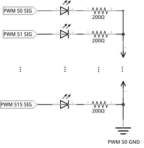
For reference, here’s a circuit diagram of our experiment:
What You’ll Need
Grab the components listed from your kit, and let’s get wiring!
- 1x Omega plugged into the Expansion Dock
- 1x Relay Expansion
- 1x Buzzer
- 1x SPDT switch
- 1x Breadboard
- 7x Jumper wires (M-M)
Hooking up the Components
The circuit for this experiment will involve wiring the Relay Expansion to both the expansion headers and the circuit. The circuit itself has two parts: one part uses the switch to send signals to the Omega, the other connects the buzzer to the Relay Expansion and operates it.
- First we’ll have to find a place on the breadboard to place the buzzer, we chose row 1 and mounted the buzzer across the middle channel.
- Taking note where the cathode (+) and where the anode (-) is, we’ll have to make sure the right wires go in the right terminal.
- Connect the anode of the buzzer to the
GNDrail on your breadboard with a jumper. The cathode will be getting signal, so we’ll deal with that later. - Next the SPDT switch needs to go into the breadboard, with each pin plugged into a different row. We chose row 5-7.
- Connect row 5 to the
GNDrail, and leave the other rows for now.
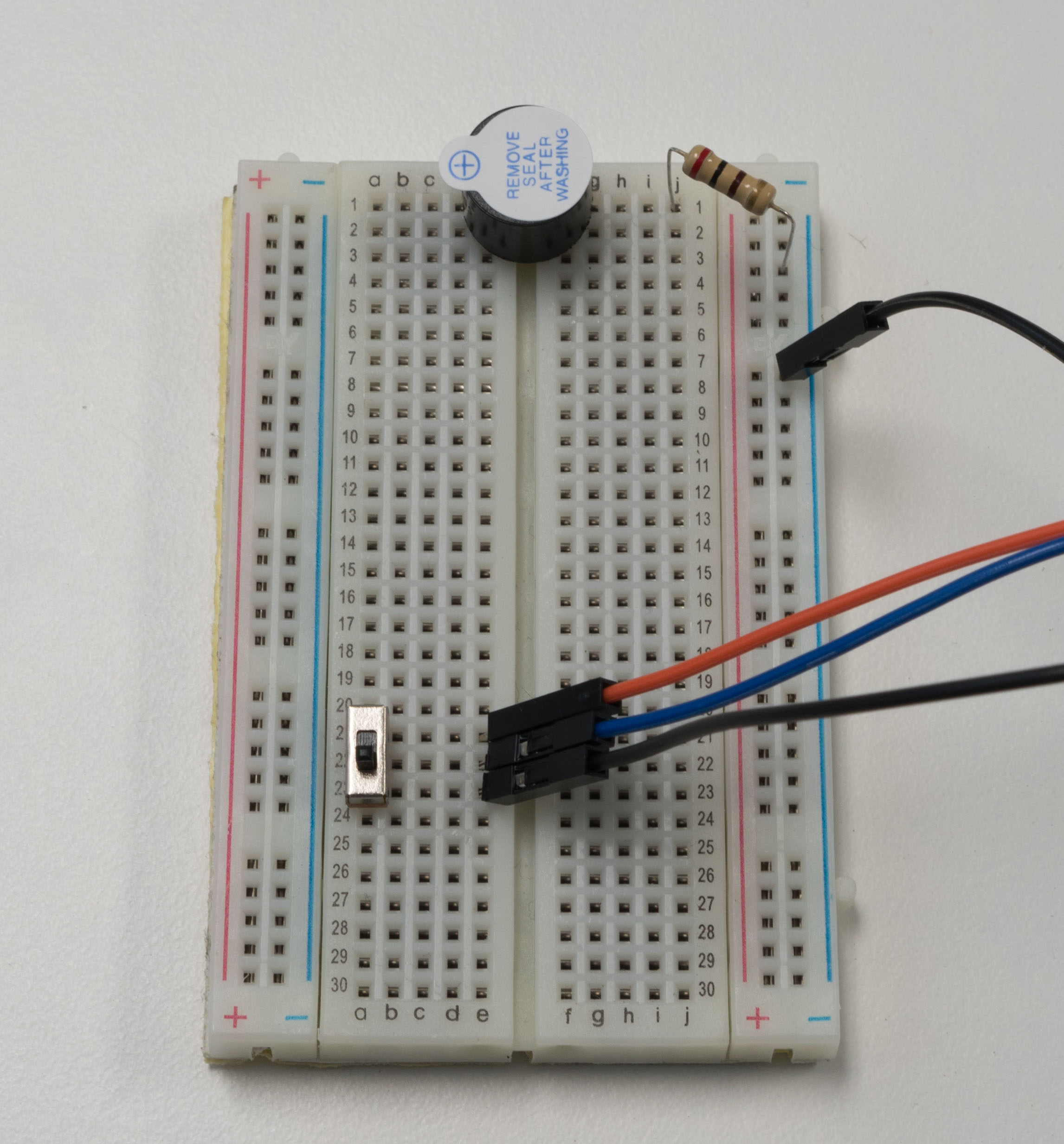
The circuit should look something like this:
Now let’s connect the buzzer circuit to the Relay Expansion. We’ll be using channel 0, with all switches on the relay set to OFF. We’ve included a diagram below to help out.
- To set up the relay, turn the screw on the
INterminal counterclockwise until the metal clamp inside is sitting a bit less than halfway in the bottom of the housing, not too much or the screw might pop out.- If you’re unsure, close the terminal all the way by turning the screw clockwise until you can’t anymore, then open it.
- Grab a male-to-male jumper wire (we prefer red or orange, as it is the convention for power wires) and insert one end into the
INterminal - Turn the screw clockwise until the wire is tightly clamped.
- Repeat for the
OUTterminal.
Once the relay is set up, let’s connect our circuit to it:
- First, grab a jumper wire (preferably black, according to convention for ground wires) and connect one end to the
GNDpin on the Dock, and the other to theGNDrail on the breadboard. - Connect the middle row of the SPDT switch (row 6) to GPIO0 on the Dock using a M-M jumper.
- Take the jumper connected to the
OUTterminal of the Relay Expansion and connect the free end to the cathode of the buzzer. We have it plugged into row 1 column C. - Take the jumper connected to the
INterminal, and plug that into the5Vpin on the Dock - this line will deliver power to the buzzer when the relay is switched on. - Grab a red or orange jumper and plug one end into the
3.3Vpin on the Dock. - Plug the other end into remaining empty pin of the switch. We plugged it into row 7 - this will be the ‘HIGH’ position of the switch.
With that, we’re all done!
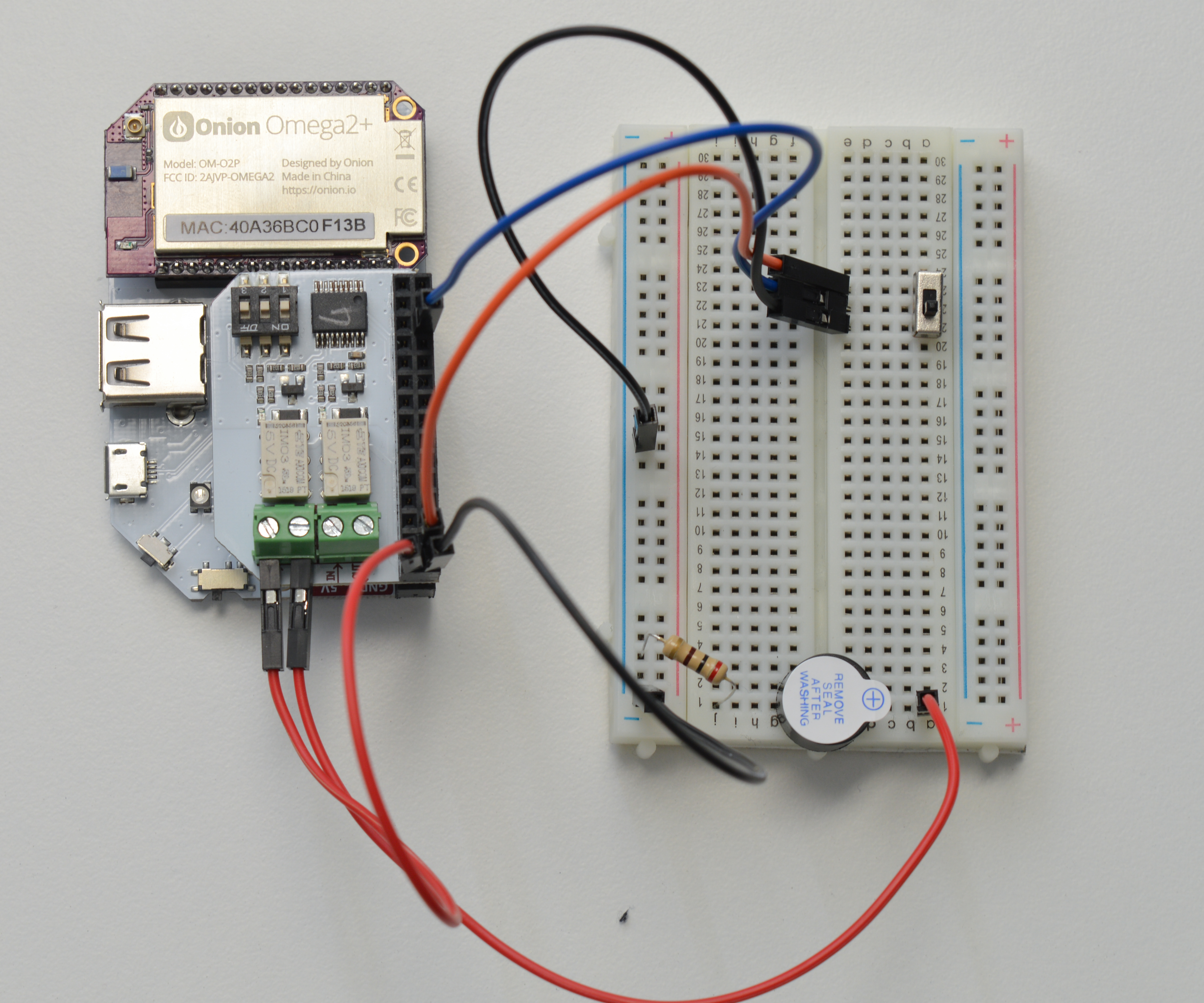
Here’s a picture of our completed circuit:
Writing the Code
The code we’ll be using is a bit more complicated than you may think. So to simplify the operation of the Relay Expansion, we leverage the relayExp class from the OmegaExpansion Python Module. For more details on the Relay Expansion Python Module, check out the software module reference in the Omega2 Docs.
For this experiment, it would be reasonable to assume that we will check the state of the SPDT switch and then set the buzzer accordingly. We won’t be doing that.
Instead, we’ll first read the state of the relay to make sure the state is different from the switch state, and then switch the Relay if needed. We’ll cover why we do this below - but before we do, let’s get to the action!
Create a file called MAK07-relayCircuit.py and paste the following code in it:
from onionGpio import OnionGpio
from OmegaExpansion import relayExp

# the GPIO to which the switch is connected
SWITCH_PIN = 0
# the value that corresponds to the Relay Expansion address switch setting
RELAY_ID = 7
# the channel on the Relay Expansion we will be using
RELAY_CHANNEL = 0
outputStrings = ['off', 'on']

def main():
    # instantiate a gpio object to interact with our switch
    switch = OnionGpio(SWITCH_PIN)    # This works because we directly imported
                                      # the OnionGpio class from the module

    # set the switch GPIO to an input, exit if the pin returns an error
    bSwitch = switch.setInputDirection()
    print ("Setting GPIO pin " + str(SWITCH_PIN) + " to input.")
    if (bSwitch is False):
        print ("GPIO set direction error.")
        return
    print ("Pin set.")

    # check if the Relay Expansion has been initialized
    bRelay = relayExp.checkInit(RELAY_ID)
    print ("Checking Relay Expansion with address 0x2" + str(RELAY_ID) + " status.")
    if (bRelay is False):
        # initialize the Expansion
        bInit = relayExp.driverInit(RELAY_ID)
        print ("Initializing Relay")
        if (bInit is False):
            # exit if the Expansion responds with an error
            print ("Relay initialization failure.")
            return
    print ("Relay initialized.")


    while (True):
        # getValue() returns a string with predictable formatting,
        # so we can convert it to int without trouble
        switchState = int(switch.getValue(), 10)
        # read the state of our relay
        relayState = relayExp.readChannel(RELAY_ID, RELAY_CHANNEL)

        # only take action if the switch and relay states are different
        if (switchState is not relayState):
            # set the relay to the state dictated by the switch
            status = relayExp.setChannel(RELAY_ID, RELAY_CHANNEL, switchState)
            if (status is False):
                print ("Error switching relay, the script will now exit.")
                break
            else:
                print ("Switch flipped, turning relay " + outputStrings[switchState] + ".")

    # turn off the relay at the end of the program
    relayExp.setChannel(RELAY_ID, RELAY_CHANNEL, 0)


if __name__ == "__main__":
    main()
What to Expect
When the script is running, you’ll see a ton of debug messages from the console. Now when you flick the switch to on or off, the buzzer should respond by turning on or off appropriately.
Infinite loop appears here as well, and as usual, exit the script with Ctrl-C.
A Closer Look at the Code
From the PWM expriments, we’ve touched on how to account for the limitations of hardware when writing software. In this expriment we’ve put more of that into practice. One important thing introduced is the Read - Modify - Write cycle. One major part of the cycle is checking status of our components (the ‘read’ part of the cycle). Additionally, we log the status. This is a very good habit to get into for fast debugging because we can use that output to quickly tell if and where something is going wrong.
Reading then Writing
Almost always, when we want to switch hardware states in software, the program has no implicit knowledge of the state the hardware is in already. To make sure hardware functions properly, and no false signals or badly timed signals are sent, the software should (as a rule) read the state of the hardware first before making changes.
This concept is known as Reading then Writing, and it actually applies to a lot of situations even in software. Multithreading, database updating, and filling and receiving forms all use this concept to try and ensure intended signals are sent, and no false signals get let through.
Checking Status
You’ll notice that of all the code, only about 5 lines are directly dedicated to changing the state of the relay! The bulk of the code is actually all about checking the states and making decisions off of that information. The reason is simple: we want to make sure the commands we send to the hardware are absolutely correct, since hardware errors are difficult to recover from! Software can be written, started, and restarted fairly quickly; but if you burn out an LED, it’s gone for good.
That’s why we consider all the variables in this circuit by reading from the relay and the GPIO pins first and make sure to only change the state of the relay when it’s safe, and it makes sense to do so. Of course when this circuit is properly wired, there’s very little that can go wrong through bad signals, but it’s always good practice to make sure.
In this case, no harm will be done to the Relay by telling it to turn on when it is already on. But this is not always the case, so it’s best to get into the habit now than have something break down the line by forgetting to check state first!
Logging Errors and Successes
There’s often a great deal of difference between what we expect our software to do versus what our software actually does. Logging is how we can try to match the expected behaviour with actual behaviour. Printing out values of variables, messages of success and failures, we bring what is normally hidden to light. This way, we can follow our code as it runs and make sure it’s doing what we really want.
Let’s say our program has a bug: the relay doesn’t turn on or off when we flip the switch. How would we log the program, what places matter? A good place to start is to print unique messages at different points of the program (especially before and after important lines of code) to let us know what order the program is doing things in. Especially the lines of code relating to the bug.
So for our example bug, if we logged the places where our code is reading and changing of the relay state, we might find that the program isn’t running any code to change the relay state at all! Armed with this information we can then go through the code and try to figure out why - hopefully leading to a solution and getting it to work!
Next time, sky’s the limit!