Controlling an LCD Screen
In this experiment, we will be building on the previous experiment by adding an LCD screen and writing a script to display the temperature sensor data on it. If you start thinking about how to run this in the background, we have something planned for that too!
Note: We will be building heavily from the temperature sensor experiment. If you haven’t done it, we highly recommend doing so, or at least giving the article a read through.
LCD Screen
The LCD screen is a 16x2 display, meaning it has 2 rows of 16 columns (characters). It has an LED backlight to illuminate the display even in the dark!
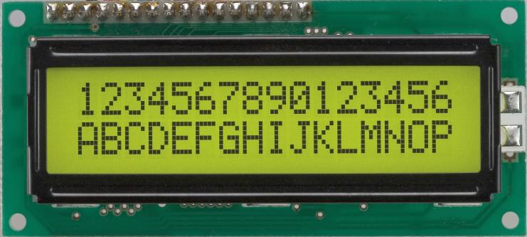
These screens are typically controlled by many parallel data lines, usually 11 or so. However, the one in your kit has additional circuitry that implements control of the screen with the I2C protocol, so you only need to use two data lines to control the screen!
I2C
I2C (Inter-Integrated Circuit), sometimes called IIC or Two-Wire Interface, is a serial interface used to quickly and easily connect multiple devices to controllers and processors such as the Omega2. Examples of I2C devices include:
- Sensors, such as temperature, humidity, current
- Actuators, such as buzzers, lights
- Controllers, such as motors, relays
Communication is performed over 2 data lanes, each given their own pin on the Omega2:
- Clock (SCL) - Signals when data is being transferred
- Data (SDA) - Carries the data to be transferred
The I2C bus uses a master-slave architecture, which means the following:
- Bus masters are devices that are in control of when and to whom they send and receive data.
- Masters send commands which include the address of the slave who should receive it.
- When using I2C with the Omega2, the Omega2 is configured to be the only bus master.
- Bus slaves are devices that respond to masters when they receive a command addressed to them.
- Each slave is identified with a hexadecimal address (eg.
0x27). - Slaves will safely ignore commands not addressed to them.
- Each slave is identified with a hexadecimal address (eg.
- Masters and slaves operate in either of two modes:
- transmit - sending data
- receive - receiving data
If you’re interested in the full details, see the Wikipedia article on I2C for more.
The Omega & I2C
All I2C interactions on the Omega2 are done using the virtual device file /dev/i2c-0. This is made possible with sysfs, a pseudo-file system that holds information about the Omega’s hardware in files, and lets the user control the hardware by editing the files.
I2C using Python
We’ve developed an I2C Python module that you can import into your apps. For all the details, see the I2C Python Module.
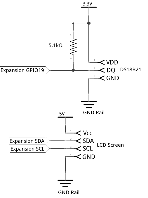
Building the Circuit
To get this experiment up and running, we’ll be using the same temperature sensor circuit from the previous experiment, but we’ll also be connecting the I2C display to the Omega so we can display the temperature on it. The code we write will tie the two together, but the build will borrow heavily from the previous experiment.
We’ll be building the following circuit:
What You’ll Need
Everything from the temperature sensor experiment:
- 1x Omega plugged into Expansion Dock
- 1x Breadboard
- 3x Jumper wires (M-M)
- 1x 5.1kΩ (yellow-purple-red) Resistor
- 1x 1-Wire temperature sensor
- Should read “Dallas 18B20” on the part
Additionally, grab the following from your kit:
- 1x LCD Screen
- 4x Jumper wires (M-F)
Hooking up the Components
The main sensor circuit is exactly the same as the previous experiment. If you’ve already taken it apart, no worries, just wire it back up exactly as before and you’ll be ready for the next step!
Once you have the temperature sensor circuit up and ready, connect the pins from the I2C display to the Expansion Dock according to this table:
| Display Pin | Expansion Dock |
|---|---|
| GND | GND |
| VCC | 5V |
| SDA | SDA |
| SCL | SCL |
Note that this time, we’re using the 5V pin instead of the 3.3V source that we’ve been using previously. This is because the display requires a higher voltage to run.
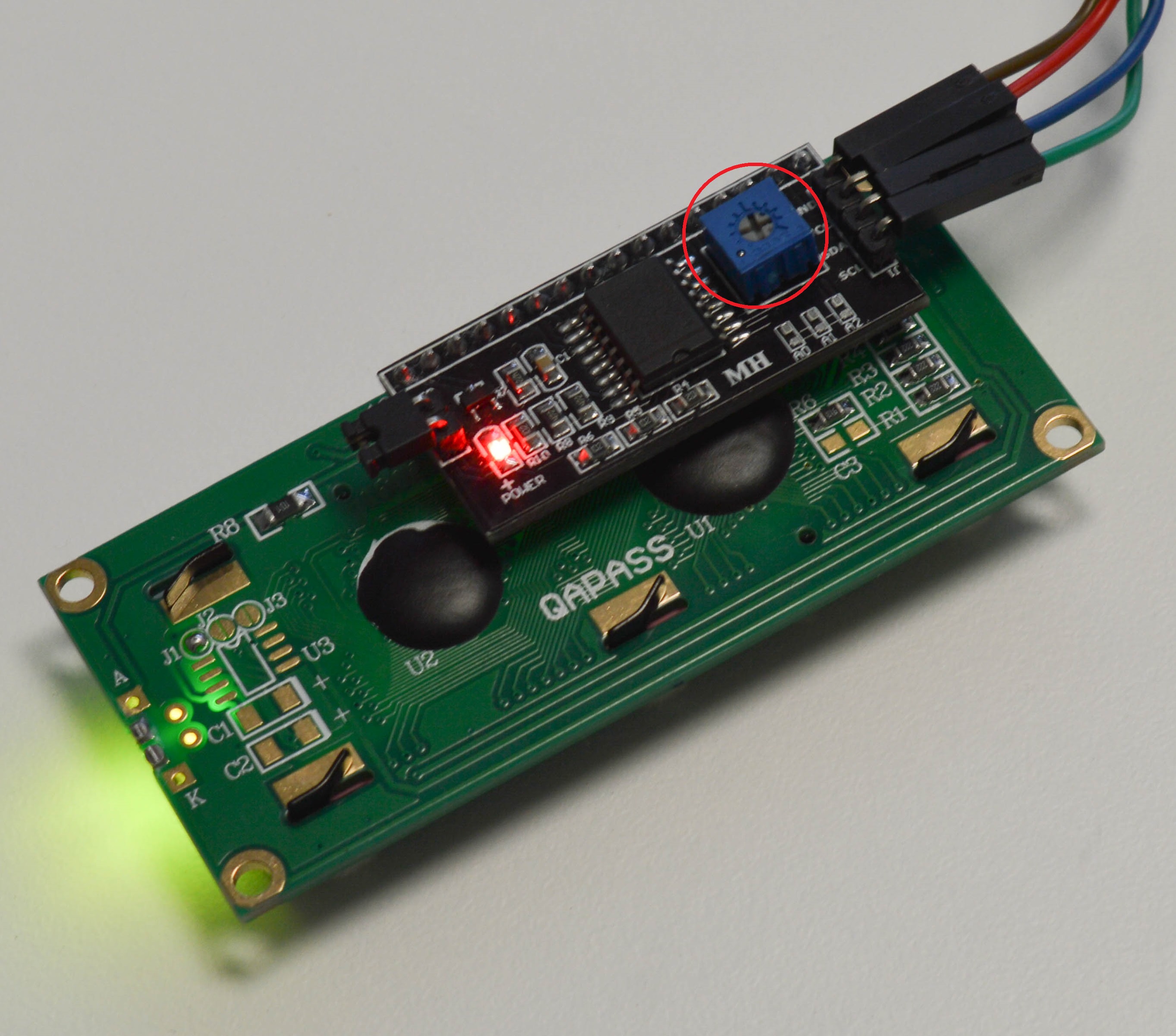
All done! If everything is connected properly, the LCD should light up with a bright green background and a row of black boxes on the top row. If it doesn’t light up, check that the jumper on the back of the LCD is firmly connected to the LED pins hanging off the side.
Your setup should look something like this:
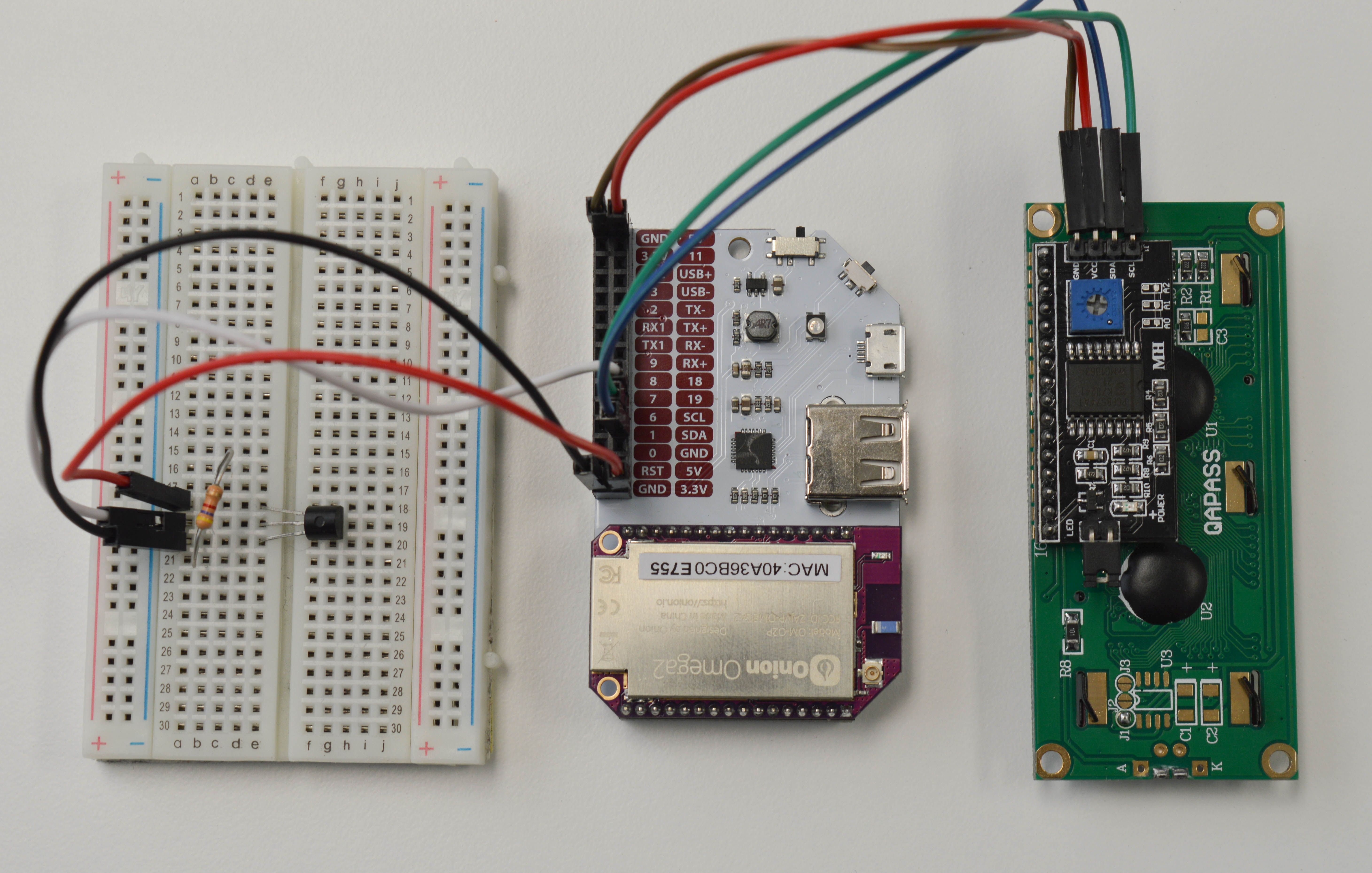
Once you’ve made sure that you’ve wired it up correctly, you can then flip over the LCD screen so that it is facing you.
If the display lights up but you can’t see any black boxes, you may need to adjust the contrast on the display. There is a small grey screw on the back; use a Philips screwdriver to turn it and adjust it so that the boxes appear. This will define how clear the text will be on the display.
Writing the Code
For this experiment, we’ll be using our Onion I2C Python Module which greatly simplifies interacting with I2C devices. If you’re curious, you can see how it works in our I2C Python module reference.
The LCD display driver code is based on user natbett’s post on the Raspberry Pi forums.
This is the plan for how we’ll implement our code:

First, let’s write a file with the low level code needed to drive the LCD display. It will contain functions to write strings and characters, and utility functions to change the behaviour of the display.
Create a file called lcdDriver.py and paste the following in it:
from OmegaExpansion import onionI2C
import time

# sleep durations
writeSleep = 0.0001 # 1 millisecond
initSleep = 0.2

## LCD Display commands
# commands
lcdClearDISPLAY = 0x01
LCD_RETURNHOME = 0x02
LCD_ENTRYMODESET = 0x04
LCD_DISPLAYCONTROL = 0x08
LCD_CURSORSHIFT = 0x10
LCD_FUNCTIONSET = 0x20
LCD_SETCGRAMADDR = 0x40
LCD_SETDDRAMADDR = 0x80

# flags for display entry mode
LCD_ENTRYRIGHT = 0x00
LCD_ENTRYLEFT = 0x02
LCD_ENTRYSHIFTINCREMENT = 0x01
LCD_ENTRYSHIFTDECREMENT = 0x00

# flags for display on/off control
LCD_DISPLAYON = 0x04
LCD_DISPLAYOFF = 0x00
LCD_CURSORON = 0x02
LCD_CURSOROFF = 0x00
LCD_BLINKON = 0x01
LCD_BLINKOFF = 0x00

# flags for display/cursor shift
LCD_DISPLAYMOVE = 0x08
LCD_CURSORMOVE = 0x00
LCD_MOVERIGHT = 0x04
LCD_MOVELEFT = 0x00

# flags for function set
LCD_8BITMODE = 0x10
LCD_4BITMODE = 0x00
LCD_2LINE = 0x08
LCD_1LINE = 0x00
LCD_5x10DOTS = 0x04
LCD_5x8DOTS = 0x00

# flags for backlight control
LCD_BACKLIGHT = 0x08
LCD_NOBACKLIGHT = 0x00

En = 0b00000100 # Enable bit
Rw = 0b00000010 # Read/Write bit
Rs = 0b00000001 # Register select bit

class Lcd:
    #initializes objects and lcd
    def __init__(self,address, port=0):
        # i2c device parameters
        self.address = address
        self.i2c = onionI2C.OnionI2C(port)

        # lcd defaults
        self.lcdbacklight = LCD_BACKLIGHT #default status
        self.line1= "";
        self.line2= "";
        self.line3= "";
        self.line4= "";

        self.lcdWrite(0x03)
        self.lcdWrite(0x03)
        self.lcdWrite(0x03)
        self.lcdWrite(0x02)

        self.lcdWrite(LCD_FUNCTIONSET | LCD_2LINE | LCD_5x8DOTS | LCD_4BITMODE)
        self.lcdWrite(LCD_DISPLAYCONTROL | LCD_DISPLAYON)
        self.lcdWrite(lcdClearDISPLAY)
        self.lcdWrite(LCD_ENTRYMODESET | LCD_ENTRYLEFT)
        time.sleep(initSleep)

    # function to write byte to the screen via I2C
    def writeBytesToLcd(self, cmd):
        self.i2c.write(self.address, [cmd])
        time.sleep(writeSleep)

    # creates an EN pulse (using I2C) to latch previously sent command
    def lcdStrobe(self, data):
        self.writeBytesToLcd(data | En | self.lcdbacklight)
        time.sleep(.0005)
        self.writeBytesToLcd(((data & ~ En) | self.lcdbacklight))
        time.sleep(.0001)

    def lcdWriteFourBits(self, data):
        # write four data bits along with backlight state to the screen
        self.writeBytesToLcd(data | self.lcdbacklight)
        # perform strobe to latch the data we just sent
        self.lcdStrobe(data)

    # function to write an 8-bit command to lcd
    def lcdWrite(self, cmd, mode=0):
        # due to how the I2C backpack expects data, we need to send the top four and bottom four bits of the command separately
        self.lcdWriteFourBits(mode | (cmd & 0xF0))
        self.lcdWriteFourBits(mode | ((cmd << 4) & 0xF0))

    # function to display a string on the screen
    def lcdDisplayString(self, string, line):
        if line == 1:
            self.line1 = string;
            self.lcdWrite(0x80)
        if line == 2:
            self.line2 = string;
            self.lcdWrite(0xC0)
        if line == 3:
            self.line3 = string;
            self.lcdWrite(0x94)
        if line == 4:
            self.line4 = string;
            self.lcdWrite(0xD4)

        for char in string:
            self.lcdWrite(ord(char), Rs)

    def lcdDisplayStringList(self, strings):
        for x in range(0, min(len(strings), 4)):
            self.lcdDisplayString(strings[x], x+1)

    # clear lcd and set to home
    def lcdClear(self):
        self.lcdWrite(lcdClearDISPLAY)
        self.lcdWrite(LCD_RETURNHOME)

    # write the current lines to the screen
    def refresh(self):
        self.lcdDisplayString(self.line1,1)
        self.lcdDisplayString(self.line2,2)
        self.lcdDisplayString(self.line3,3)
        self.lcdDisplayString(self.line4,4)

    # turn on the backlight
    def backlightOn(self):
        self.lcdbacklight = LCD_BACKLIGHT
        self.refresh()

    # turn off the backlight
    def backlightOff(self):
        self.lcdbacklight = LCD_NOBACKLIGHT
        self.refresh()
Now let’s write the main routine for the experiment. This script will create an Lcd object, and a TemperatureSensor object. It gets the sensor data from the TemperatureSensor, then sends that data to the Lcd object to display. It does this once and exactly once, so you can call it whenever for a quick update.
Create a file called STK09-temperatureLCD.py and paste the code below into it.
import lcdDriver
import oneWire
from temperatureSensor import TemperatureSensor

# default address of i2c backpack is 0x3f by default
lcdAddress = 0x3f

# setup one wire temperature sensor object
oneWireGpio = 19 # set the GPIO that we've connected the sensor to
pollingInterval = 1 # seconds

# function to read the temperature from the One-Wire Temperature Sensor
def getTemp():
    # check if 1-Wire was setup in the kernel
    if not oneWire.setupOneWire(str(oneWireGpio)):
        print "Kernel module could not be inserted. Please reboot and try again."
        return -1

    # get the address of the temperature sensor
    # it should be the only device connected in this experiment
    sensorAddress = oneWire.scanOneAddress()

    sensor = TemperatureSensor("oneWire", { "address": sensorAddress, "gpio": oneWireGpio })
    if not sensor.ready:
        print "Sensor was not set up correctly. Please make sure that your sensor is firmly connected to the GPIO specified above and try again."
        return -1

    return sensor.readValue()

# function to display the temperature on the LCD screen
def displayTemp(temp):
    # setup LCD
    lcd = lcdDriver.Lcd(lcdAddress)
    lcd.backlightOn()

    lcd.lcdDisplayStringList([
        "Temperature: ",
        str(temp) + " C"
    ])

def __main__():
    t = getTemp()
    displayTemp(t)

if __name__ == '__main__':
    __main__()
What to Expect
Calling the script will update the LCD screen with a fresh temperature reading.
Wouldn’t it be nice if something could run the script for us every minute to actually update the LCD? We will get there in a bit, but for now, let’s take a look at how the code works.
A Closer Look at the Code
Here we’ve introduced the Onion I2C module. The Python module takes care of the complexities in working with I2C devices, exposing a set of easy to work with functions. In the process, we’ve also started to let multiple objects interact with each other - actually making apparent the benefits of abstraction.
The Onion I2C Module
We wrote this module to make it easy for you to use the I2C bus. I2C based electronics are designed to operate with a minimum of instructions and very specific signalling between host and client. Our I2C modules does all the signalling and contact establishing for you so you only need to worry about sending the correct data and reading the correct registers. For a detailed look on how it works, we’ve written up a software reference to our I2C Python Module.
In the code, we specifically use two main functions of the library: the constructor and i2c.write(). The constructor creates an I2C device object with the given address. The i2c.write() function then writes a list of bytes to the device’s address (without specifying the memory location on the device). The LCD display requires specific commands in order to activate its different write modes which the lcdDriver class wraps up nicely, making our final execution script quite compact.
Multiple Different Objects
Here we’re using two objects of different classes to accomplish our goal, TemperatureSensor and Lcd. If we had other devices we wanted to include in this experiment, we can write more class definitions and load them using the import statement.
This is an incredibly common programming technique and is at the heart of Object Oriented Programming! It helps us capture and understand interactions between complex pieces through simplifying them in a human-readable way.
Although it’s a powerful tool, too much abstraction can create its own problems. Ultimately, writing smart, self-documenting code comes from lots of practise and communication between you and the people you share your work with!
Going Further: Automating the Script
We can use the cron Linux utility to automatically run the script once every minute, without having to tie up your system by leaving Python running. Since cron executes from elsewhere in the Linux system, we’ll have the give it the absolute path to our scripts.
First, take note of which directory your scripts are in by running the command pwd. If you’re developing in the /root folder, you will see:
/rootLet’s assume that you put your scripts in the /root directory. So to run our script with an absolute path, the command would be:
python /root/STK09-temperatureLCD.pyTry it out yourself:
cd /
python /root/STK09-temperatureLCD.py
Everything should work just like before. Now let’s move on to setting up cron. Run crontab -e to edit the file that contains commands and schedules to run them, and add this line to the end of the file:
* * * * * python /root/STK09-temperatureLCD.pyTo briefly explain, the asterisks (*) mean ‘for all instances’. The position of the asterisk corresponds to ‘minute’, ‘hour’, ‘date’, ‘month’, and ‘year’ in order from left to right. The path at the end is the script or command you want to run. Basically, this line tells cron to run the
STK09-temperatureLCD.pyscript once a minute.
Note that, by default, this command will load the vim text editor to edit the crontab settings.
Finally, run the following command to restart cron so it can start running your script:
/etc/init.d/cron restartYour LCD should now update once a minute, and you’re free to use your Omega for other things in the meantime!
To learn more about cron on the Omega, see the article on running a command based on a schedule in the Omega2 documentation.