Using a Shift Register to Control Multiple LEDs
Shift registers are very useful tools; using a few GPIOs connected to a shift register, we can increase the number of output data pins that are available to us.
In this experiment, we’ll be using a shift register to control eight LEDs, but we’ll only be using three GPIOs on the Omega.
Shift Register
A shift register is an external integrated circuit (IC) that can be used to expand the number of output pins available to us. Essentially they let you turn serial input from a single pin (one bit after the other) into multiple parallel output signals (all at once on separate lines).
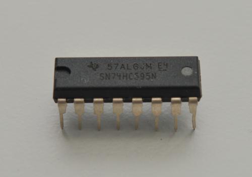
The shift register used in your kit is the popular 74HC595. It has 8 output lines which allows you to manipulate and use bytes for output in your code.
Overview
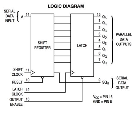
So how does this work? The IC is made up of two registers, units of memory that can hold up several binary values in order (8 for the IC in your kit). They are:
- The shift register, which holds 8 values before they are written to the output pins. Values can be “shifted” through this register from one position to the next, starting at position “A” to position “H”.
- The storage register, which takes values from the shift register and sends them to the data output lines, labelled
QAtoQH. For example, a logical1in position “C” of the storage register would create a HIGH signal onQC.
There are three pins on the IC that we use to control it with the Omega. Two of these pins are clocks: special inputs that trigger the IC to do something when they receive a signal that changes from LOW to HIGH (also known as a pulse or a rising edge).
| Pin | Name | Purpose |
|---|---|---|
| SER | Serial data pin | This is the serial data input line. When we pulse the serial clock (SRCLK), the signal on this line is stored in the 1st position (“A”) of the shift register. |
| SRCLK | Serial clock | When pulsed, shifts each value in the shift register forwards by one position, then loads the value from the SER pin into position “A”. Note that this does not change the signals on the output lines until you pulse the register clock (RCLK). |
| RCLK | Register clock, or “latch pin” | When pulsed, updates the storage register with new values from the shift register, sending a new set of signals to the 8 output pins. This happens so quickly that they all seem to change simultaneously! |
Bit Order
Keep in mind that the first value you send the shift register will be shifted towards the last output pin as you send it more data.
Let’s say we want to send the following bits: 10101010. Intuitively, it seems easiest to send each bit in the number from left to right as if it were a string. In Python, this would look something like:
bytestring = '10101010'
bytestring = list(bytestring) # turns the string into a list: ["1", "0", "1", "0", ...]
for bit in bytestring:
    shift(bit)          # sends 1, then 0, then 1, then 0, ...
However, sending it this way means that after we’ve sent all eight, the 1st bit would actually be shifted all the way to the last output (QH), the 2nd bit would be shifted to the 2nd-to-last output (QG), and so on until everything is reversed! This way of shifting values out is known as most-significant bit (MSB) first. If we used this method in our shift register class, we would have to wire everything up backwards, and this could make it confusing to assemble or debug circuits.
We can get around this issue by sending the rightmost, or least significant bit (LSB), first. We can modify the above code into something like this:
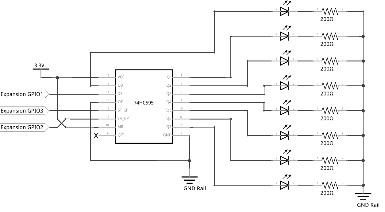
Pinout Diagram
The pinout diagram for the 74HC595 is shown below:
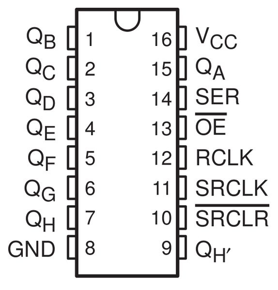
On the right side of the chip, you can see the three control pins described above, as well as the first output (QA). On the left side, you can see the other 7 outputs (QB - QH).
Controlling a Shift Register
So how can this let us control multiple outputs with one data pin? Well, let’s say we have 8 LEDs hooked up to the data lines, and we want to turn on the 2nd, 4th, and the 8th LEDs like so:
| LED | Data Line | Desired Value |
|---|---|---|
| 1 | QA | LOW |
| 2 | QB | HIGH |
| 3 | QC | LOW |
| 4 | QD | HIGH |
| 5 | QE | LOW |
| 6 | QF | LOW |
| 7 | QG | LOW |
| 8 | QH | HIGH |
First, we’ll clear out the register so all LEDs are off by writing eight 0’s to the shift register, then pulsing the latch pin to write the outputs to the data lines. This is done by setting and holding SER LOW, then pulsing SRCLK 8 times, then pulsing RCLK once.
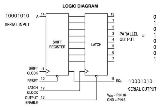
Then, using the LSB method, we will reverse the bytestring to get 10001010. For each of these values:
- Set SER to the specified value (HIGH or LOW).
- Pulse SRCLK from LOW to HIGH to shift the value of SER into the shift register.
We repeat the 2 steps above (for example, by using a loop) until all 8 values have been shifted in. Then pulse the RCLK pin to write these values to the storage register and data lines, which turns on the LEDs!
In this way, we can control up to 8 different outputs with only 3 GPIOs. This is an incredibly powerful technique that you can use to work with many components at once.
Here’s the diagram from before to summarize what we’ve just described.
Daisy-Chaining
Shift registers can also be connected in series to each other to extend the number of data lines that can be controlled at once. We can do this by using the QH' pin, which is connected inside the shift register to the last output QH.
Simply connect the SER pin of one shift register to the QH' pin on another, and connect their SRCLK and RCLK pins together. That way, when you pulse SRCLK, the 2nd chip will read from the last output of the 1st, and when you pulse RCLK, both chips will update their output lines. This is great because this does not require any additional GPIOs from the Omega!
You’ve now just created a 16-bit shift register, and you can extend the chain further by adding more chips in the same way as above. This is known as daisy-chaining.
Detailed Specifications
if you’re curious about the clock cycle timings or other information about the IC, you can refer to the datasheet for the SN74HC595 shift register. The clock cycle timing diagram can be found on page 8.
Building the Circuit
This circuit is quite involved but we’re going to split it up into 3 parts:
- Connecting the shift register
- Connecting the LEDs
- Connecting your Omega
It’s going to be similar to the second experiment, but this time we’re going to use 8 LEDs and a shift register. Refer to the circuit building instructions in Experiment 2, except you will be connecting 8 LEDs to the shift register instead of the Omega’s GPIOs.
The GPIOs that are going to be used in this experiment are:
- 1
- 2
- 3
What You’ll Need
We’ll be building a circuit on your breadboard using the following components:
- Omega2 plugged into Expansion Dock
- Breadboard
- Shift Register
- 8x LEDs
- 17x M-M Jumper Wires
- 8x 200Ω Resistors
Hooking up the Components
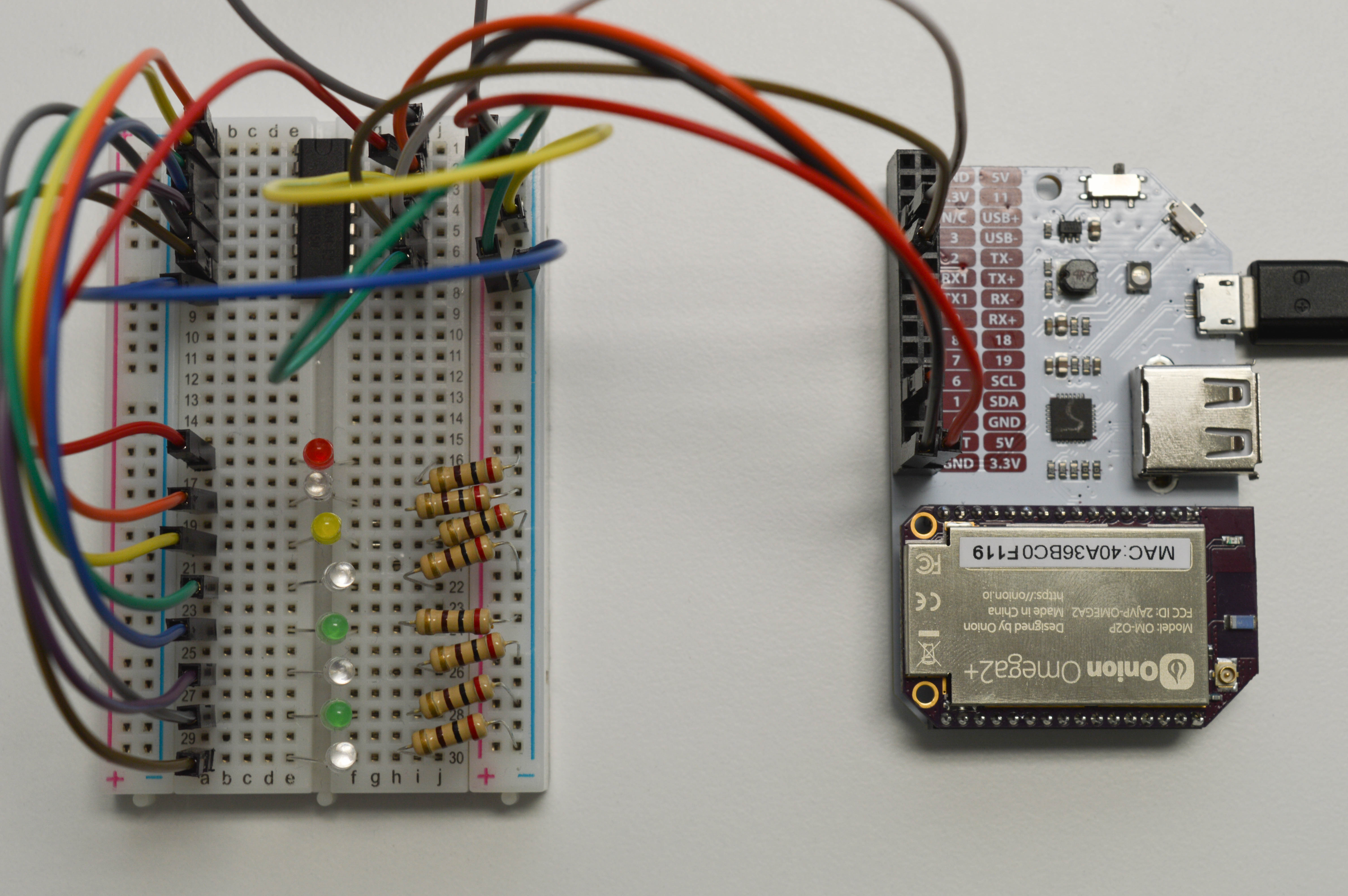
This is how the circuit is going to be arranged:
Before we get to working with our fancy chip, we need to learn how to properly orient them on the breadboard so we don’t plug them in upside-down!
IC Direction Indicator
Integrated circuits (ICs) such as shift registers and H-bridges can come in dual in-line packaging with little metal legs for pins. It is crucial that ICs are plugged in right-side-up, so to avoid connecting them upside-down, they typically have a small semi-circle indentation on one of the ends that indicates “up”.
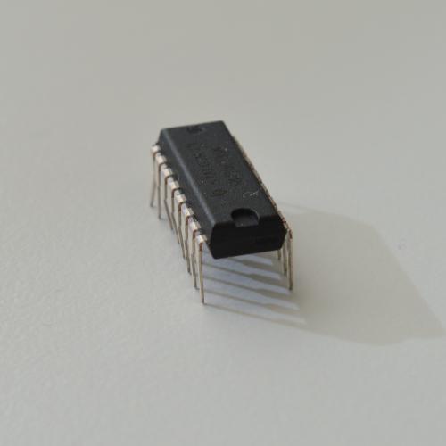
Diagrams that show which pin does what (known as “pinout diagrams”) will also typically show this marker so that you can always tell which pin is which.
Before you plug in an IC, make sure that this marker is towards the top of the breadboard. Otherwise, the instructions might be misinterpreted and pins will be connected to places they shouldn’t be!
When plugging in any IC into a breadboard, it should be plugged in across the gap in the middle. If you don’t do this, you will short-circuit the pins of your IC (remember that the rows on each side are all shorted).
You may need to bend the pins just a bit in order to get it to fit. Don’t worry about it so much; electronics are actually pretty tough and won’t be hurt by a little bit of manual pin bending.
There are several wiring connections you’ll need to hook up, so we’ll go through it step by step. We’ll be referring to each pin by the numbers provided in the pinout diagram above.
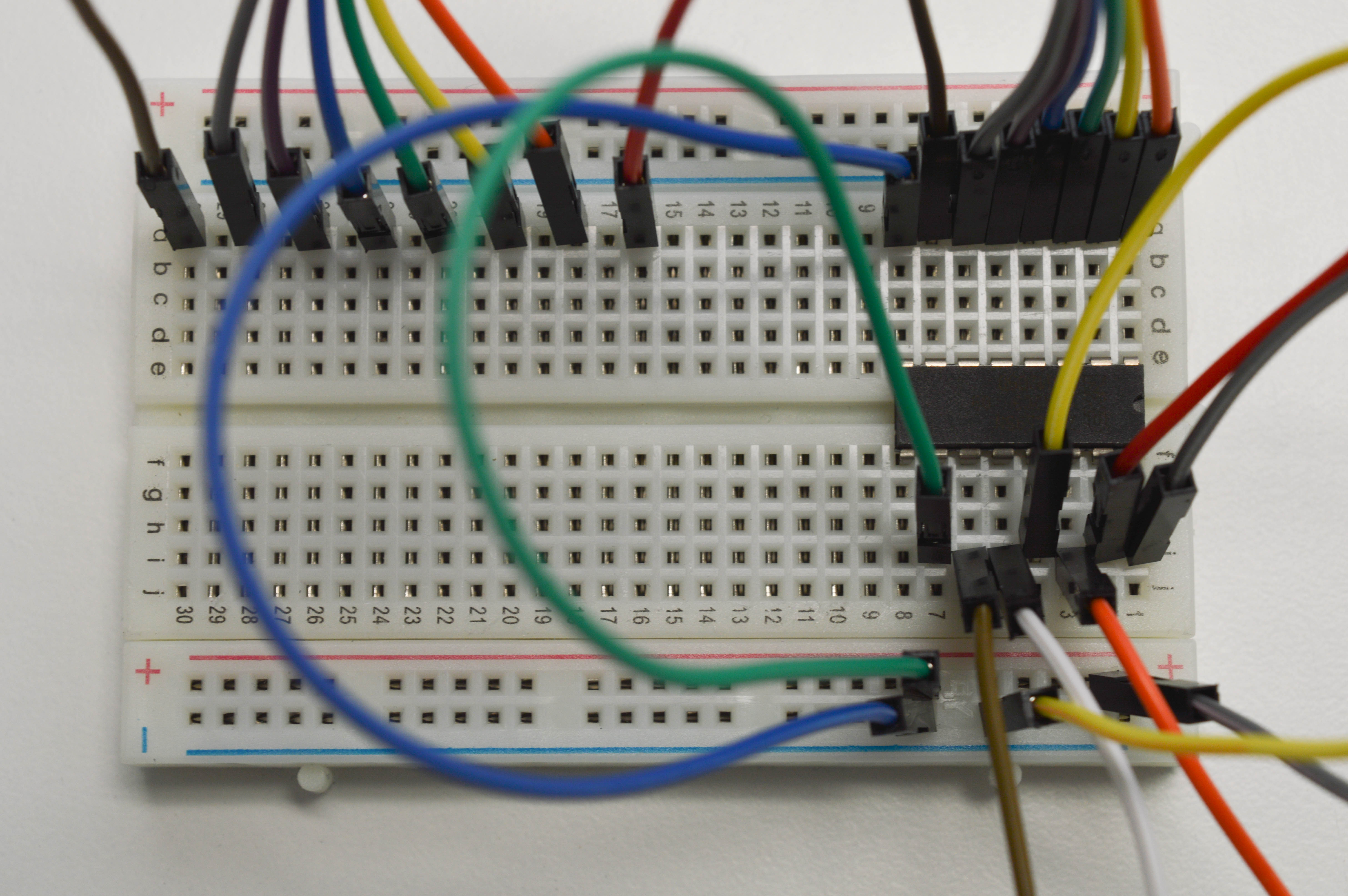
Connecting your Shift Register
- Make sure the little “indent” on the chip is pointing towards the top of the breadboard.
- Plug in the chip at the top of the breadboard across the gap so that the pins sit in rows 1 through 8.
- Connect
Vcc(pin 16) andSRCLR(pin 10) to the+(Vcc) rail. - Connect
GND(pin 8) andOE(pin 13) to the-(ground) rail.
Once you have completed the above steps, add some M-M jumper wires from the 8 outputs QA - QH to 8 empty rows on the breadboard.
Your circuit should look something like this:
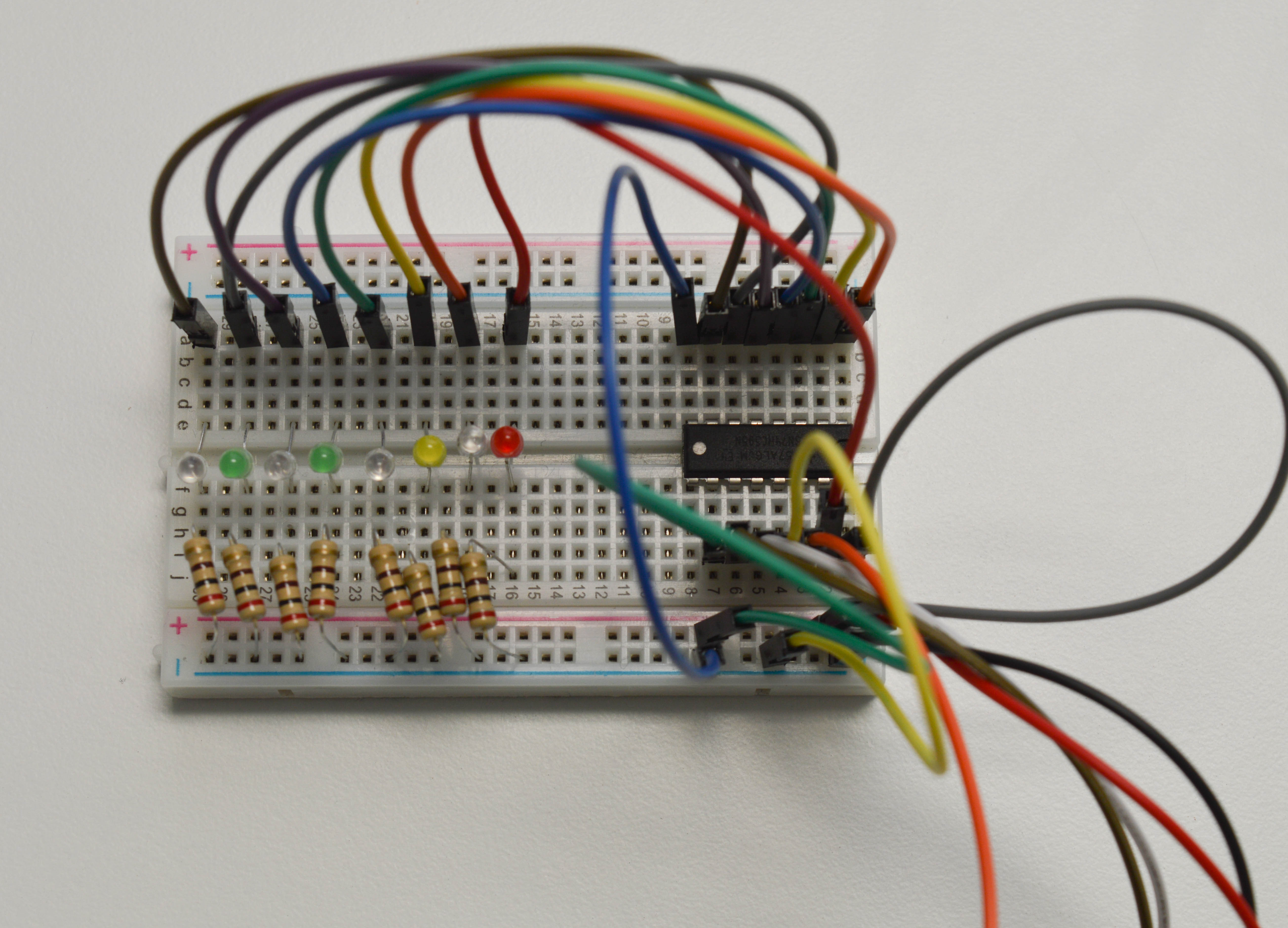
Connecting your LEDs
- Connect 8 LEDs the same way we did in experiment 2, starting at row 16 on the breadboard and going down.
- When connecting them, do it the other way around: with the cathodes on the right side and the anodes on the left side. This will make our wiring easier later.
- Connect the jumper wires from the shift register’s data lines according to the following table:
| Pin Name | Pin # | LED # |
|---|---|---|
| QA | 15 | 1 |
| QB | 1 | 2 |
| QC | 2 | 3 |
| QD | 3 | 4 |
| QE | 4 | 5 |
| QF | 5 | 6 |
| QG | 6 | 7 |
| QH | 7 | 8 |
The wire for QA starts on the right side of the chip and goes to the 1st LED, while the wires for the other 7 start on the left side and should go straight down the breadboard.
Your circuit should now look like this:
Connecting your Omega to the Shift Register
- Connect the GND pin on the Expansion Dock to the ground rail.
- Connect GPIO1 to
SER(pin 14). - Connect GPIO2 to
SRCLK(pin 11). - Connect GPIO3 to
RCLK(pin 12). - Connect the 3.3V pin on the Expansion Dock to the Vcc rail.
And there you have it, it’s all wired up and ready to run! Now let’s take a look at the code we’re going to write.
Writing the Code
Our code will be split into two files; one for our main program, and one for our shift register. We’ll start with the shift register file. Create a file in your root directory named registerClass.py and copy the code below into its contents:
import onionGpio

# class to control a shift register chip
class shiftRegister:
    # instantiates the GPIO objects based on the pin numbers
    def __init__(self, dataPin, serialClock, registerClock):
        self.ser = onionGpio.OnionGpio(dataPin)
        self.srclk = onionGpio.OnionGpio(serialClock)
        self.rclk = onionGpio.OnionGpio(registerClock)
        self.setup()

    # Pulses the latchpin - write the outputs to the data lines
    def latch(self):
        self.rclk.setValue(0)
        self.rclk.setValue(1)
        self.rclk.setValue(0)

    # Clear all the LEDS by pulsing the Serial Clock 8 times in and then the rclk once
    def clear(self):
        self.ser.setValue(0)
        for x in range(0, 8): #Clears out all the values currently in the register
            self.srclk.setValue(0)
            self.srclk.setValue(1)
            self.srclk.setValue(0)

        self.latch()

    # sets the GPIOs to output with an initial value of zero
    def setup(self):
        self.ser.setOutputDirection(0)
        self.srclk.setOutputDirection(0)
        self.rclk.setOutputDirection(0)

        self.clear()

    # push a bit into the shift register
    #   sets the serial pin to the correct value and then pulses the serial clock to shift it in
    def inputBit(self, inputValue):
        self.ser.setValue(inputValue)
        self.srclk.setValue(0)
        self.srclk.setValue(1)
        self.srclk.setValue(0)


    # push a byte to the shift regiter
    #   splits the input values into individual values and inputs them. Then pulses the latch pin to show the output.
    def outputBits(self, inputString):
        bitList = list(inputString) # Splits the string into a list of individual characters ("11000000" -> ["1","1","0","0","0","0","0","0"])
        bitList = bitList[::-1]      # reverses the string to send LSB first
        for bit in bitList:
            bit = int(bit) # Transforms the character back into an int ("1" -> 1)
            self.inputBit(bit)
        self.latch()
This file contains a single class that allows us to use and reuse it wherever we like. The main component here is the __init__ function which initializes the class object.
Now let’s write the main script. Create a file in the same directory called STK06-using-shift-register.py and paste the following code in it:
from registerClass import shiftRegister
import signal

# instantiate a shift register object
#   Data pin is GPIO 1, serial clock pin is GPIO 2, Latch pin is GPIO 3
shiftRegister = shiftRegister(1,2,3)

# Signal interrupt handler to exit after the animation has finished when Ctrl-C is pressed
def signal_handler(signal, frame):
    global interrupted
    interrupted = True

signal.signal(signal.SIGINT, signal_handler)


# To create the animation on the LEDs through the shift register,
# we use a binary number instead of a string. We can move the lights
# around by bitshfting instead of string operations.
value = 0b11000000
interrupted = False

# infinite loop - runs main program code continuously
while True:
    # this animation has 12 different frames, so we'll loop through each one
    for x in range(0, 12):
        # we need to transform the binary value into a string only when sending it to the shift register
        bytestring = format(value, '08b')
        shiftRegister.outputBits(bytestring)
        # now we are free to manipulate the binary number using bitshifts

        # if in the first half (6 frames) of the animation, move the LEDs to the right
        if x < 6:
            value >>= 1 # Shifts all digits right by one (11000000 -> 01100000)
        # else we must be in the second half, so move the LEDs to the left
        else:
            value <<= 1 # Shifts all digits left by one (01100000 -> 11000000)
    # interrupt (Ctrl-C) handler
    if interrupted:
        shiftRegister.clear() # turn off the LEDs
        break
The main program loads the class we wrote and creates a shiftRegister object. We then use that object to control our LEDs through the shift register.
What to Expect
What this will do is light up two of your LEDs, and then move them all the way to one side, and back again (think Kitt from Knight Rider).
You can terminate the code by pressing Ctrl-C or Cmd-C on Mac OS.
A Closer Look at the Code
We’ve introduced some new and important concepts in this experiment.
We’ve created and imported modules, files containing code that can be loaded and reused in other scripts without us having to re-type them again. We’ve also introduced classes which are blueprints for Python objects. Python objects are collections of data that are meant to help you wrap up low-level grunt-work code into simpler, more usable functions and variables.
Modules and classes are a crucial part of writing clean and maintainable software. It’s best practice to write your code to make use of modules or classes and avoid retyping the same code over and over again so you can update or make fixes much more easily.
During the code, we used bitshifting as an optimization to avoid slow String operations.
Finally, we introduced safely exiting from an infinite loop, to ensure that the Omega’s GPIOs are properly freed from the Python script once you want to end the program.
Creating and Importing Modules
A module is a file containing Python definitions and statements. This can be used to split your project into multiple files for easier maintenance. The registerClass.py file is an example of a self-made module that we’ve imported. Some modules are built in to Python; some examples are time which you may have used before, and signal which is used in our main program.
Some modules are built into the Python system and can be imported by name no matter what directory your script is in, such as time or sys. However, if you create your own module file, you can import it by name only if it is in the same directory as the script that calls it. Otherwise you will need to use a slightly different command where you must provide the filepath to the module file.
In order to keep things simple, we will be creating module files in the same directories as the main scripts for all of these experiments.
Creating and Using Classes
As a refresher, classes are a way to create a template for creating reusable objects in our code. So far, we’ve been using the onionGpio class that we at Onion made to make your development experience easier. This class includes clean, easy-to-use functions such as setValue() that hide away boring and time-consuming system calls from you, the up-and-coming programmer who wants to get to the fun stuff!
Here, we’ve gone one step further by creating our own class called shiftRegister that also uses the onionGpio class in order to create our shift register objects. This is because in this case, we’re more interested in the data we send to the shift register than controlling the shift register’s GPIOs!
If we wanted to connect another shift register to our circuit, we can control it as easily as the first by creating another shiftRegister object.
After creating an object, we get access to the functions defined by the object’s class. We can call these functions through our instantiated object like in this example:
This function is defined in the shiftRegister class file:
def outputBits(self, inputString):
    bitList = list(inputString) # Splits the string into a list of individual characters ("11000000" -> ["1","1","0","0","0","0","0","0"])
    for x in bitList:
        x = int(x) # Transforms the character back into an int ("1" -> 1)
        self.inputBit(x)
    self.latch()
You’ll also notice that we include self in our Python class functions. This is necessary so that we are always working with variables or functions pertaining to the current object. This is called explicit self in Python.
Binary Numbers
Binary numbers are numbers whose digits can only be 0 or 1. Similar to how the decimal or base 10 system where each digit is a power of ten, each digit (or bit) in binary is a power of 2. Take a look at some of the conversions from binary to decimal below:
| Binary | Decimal |
|---|---|
| 1 | 1 |
| 10 | 2 |
| 100 | 4 |
| 1000 | 8 |
When writing binary numbers in code, they’re typically prefixed with a 0b, like 0b11010. When assigning integers such as 42 to variables, the computer actually stores them as binary numbers (42 = 0b101010); you can then work with them in either binary, decimal, or even a different base if you wish!
A byte is an 8-bit binary number, for example 0b11000000. A bytestring is a string representation that we can perform string operations on, such as reading each bit one at a time.
Bitshifting
You’ll notice we do some funky operations with the value variable like so:
value >>= 1 # Shifts all digits right by one (11000000 -> 01100000)
...
value <<= 1 # Shifts all digits left by one (01100000 -> 11000000)
The >> operation by itself is known as the bitshift operator.
Bitshifting is a pretty low level operation that moves the bits of a binary value left or right. In our script, our shift register command starts off as the number 0b11000000. For example, to bitshift one digit to the right, we move both of the two 1s right one place to get 0b00110000. Bitshifting is a fast operation for computers to do, and is easier than trying to convert the number into a binary string and moving the characters around by hand.
The added = sign means the same thing as in the increment operator +=. It performs the bitshift operation on the variable and updates it without you having to explicitly reassign it.
On a side note, when we bitshift a number to the left or right, we’re actually multiplying or dividing it by 2 respectively! This is like multiplying or dividing by 10 in the decimal system where the digits shift left and right.
While it’s usually a good deal faster, bitshifting isn’t always the most readable code - since the purpose of the shift is not often clear. Remember to comment your code so you and others can understand why it’s there!
Exiting Infinite Loops
When using GPIOs, it’s important that you exit your code properly to free the GPIOs back to the filesystem for use by other programs. This can be quite difficult when we create an infinite loop so we’ve included a solution to that.
When inspecting our main program we see a function defined as signal_handler. We also see an signal listener in the form of:
signal.signal(signal.SIGINT, signal_handler)This listener is waiting for an interrupt from the user in order to run the signal handler code. When you enter Ctrl-C or Cmd-C you are sending a keyboard interrupt which is then handled by the interrupt handler function in order to exit the program in a safe way. This way your code will always finish the current left-right animation before exiting, thus making sure that your GPIOs are properly freed by the time the program exits.