Relay Expansion
The Relay Expansion allows you to control two other independent, external circuits using the Omega. These circuits are safely isolated from the Omega and can be either lower or higher voltage; see the maximum ratings in the table in the article below for more details.
Never exceed the maximum electrical ratings of the relays or you risk damaging the Relay Expansion, Omega, or even starting a fire.
This Expansion communicates with the Omega using the I2C protocol. The Expansion’s I2C device address is configurable by the address switches and ranges from 0x20 to 0x27. If you’re curious, check out the article on I2C.
The Relay Expansion is designed so you can stack multiple Relay Expansions onto the same Omega. Each board comes with a small switch used to give it a unique address, and up to 8 Relay Expansions can be controlled by a single Omega. This means you can control up to 16 external circuits and devices!
The Hardware
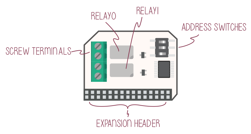
The Relay Expansion comes with two electromagnetic relays with screw terminals.
Connecting to a Dock
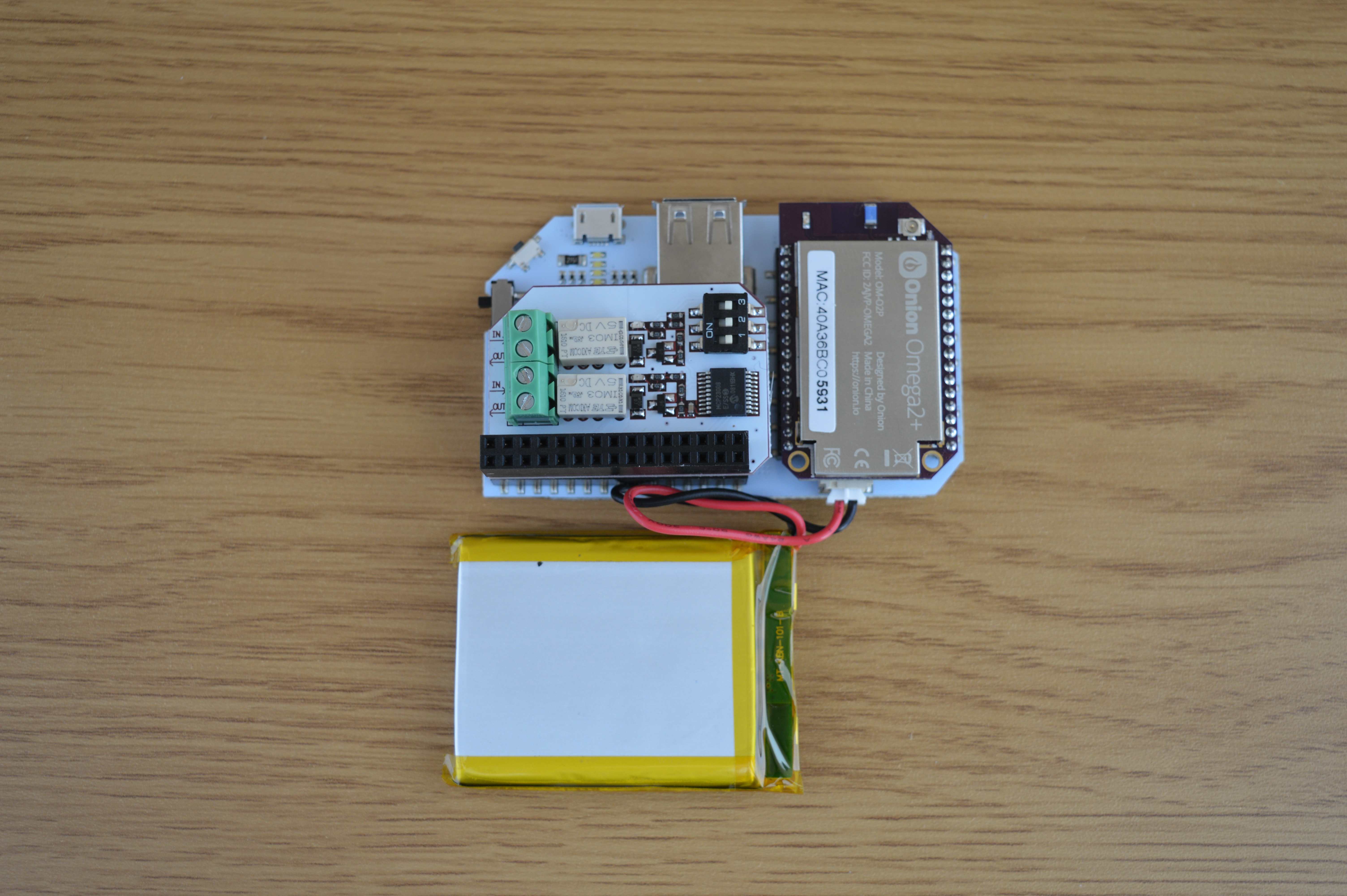
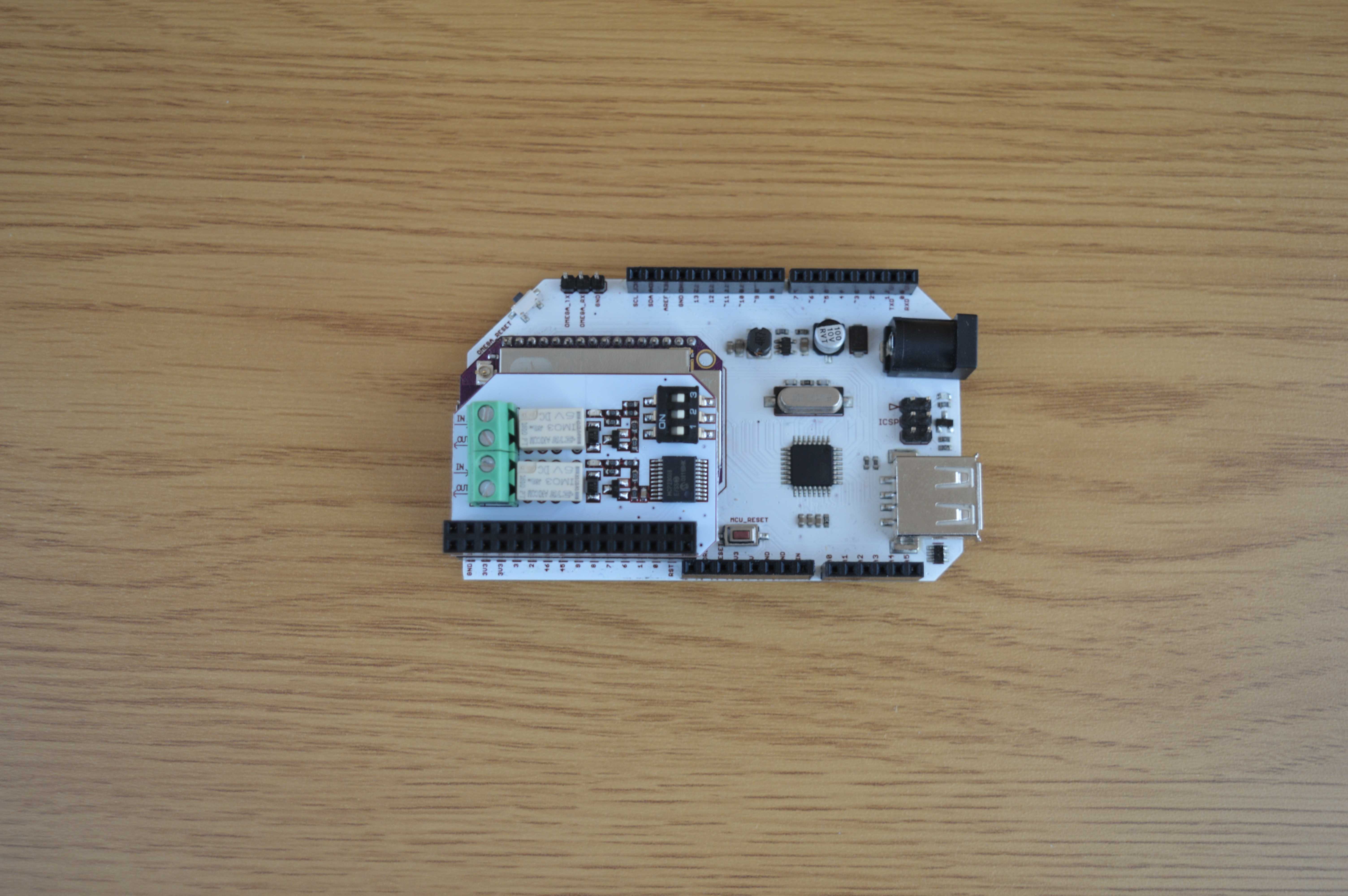
You can use the Relay Expansion with the Expansion Dock, Power Dock, or Arduino Dock R2. You can also safely stack other Expansions on top of it.

To connect the Relay Expansion to the Omega, plug it into the Expansion Header on the Expansion Dock.
The Relays
Relays are simple switches that can open (disconnect) and close (connect) circuits. Take the following example circuit:

In the above diagram, the function of the Switch can be performed by a single relay.
The Relay Expansion uses two TE Axicom IM03 relay modules. Some of the specifications are shown below:
| Parameter | Specification |
|---|---|
| Maximum Switching Voltage | 220VDC, 250VAC |
| Current Rating | 2A |
| Switching Power | 60W, 62.5VA |
| Switching Time | Typical: 1ms Maximum: 3ms |
For full specifications, please see the TE Axicom datasheet.
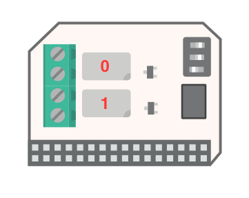
The relays channels are labelled below:
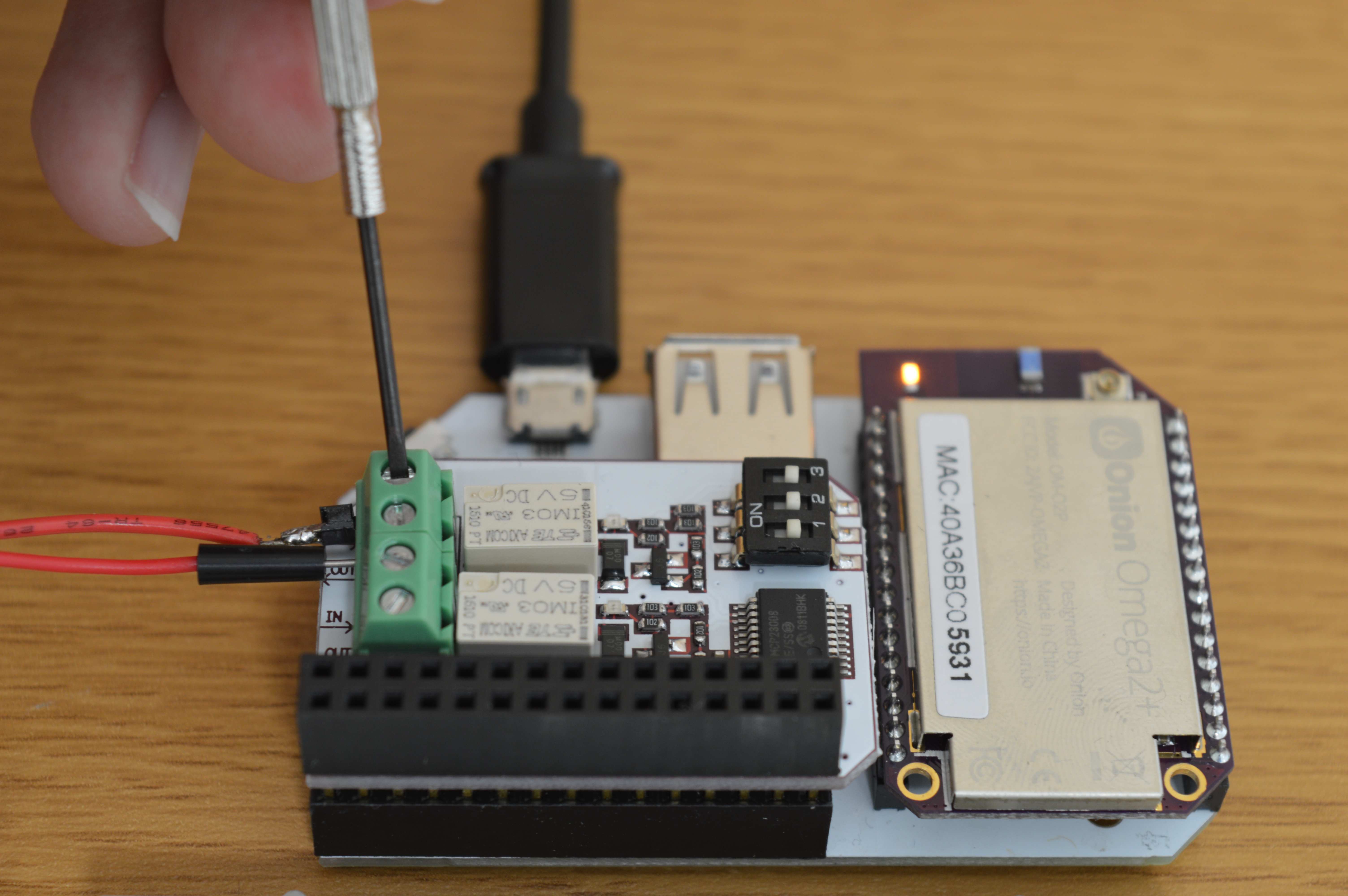
The Screw Terminals
The green block on the board is called the terminal block. It houses 4 terminals, 2 for each relay, into which you plug your circuit wires. To secure the wires inside the terminal block, screw them down with a small flathead screwdriver.
The Address Switch
The address switch allows you to change the I2C address of the board. This is needed to differentiate multiple Relay Expansions from each other when connected to the same Omega.
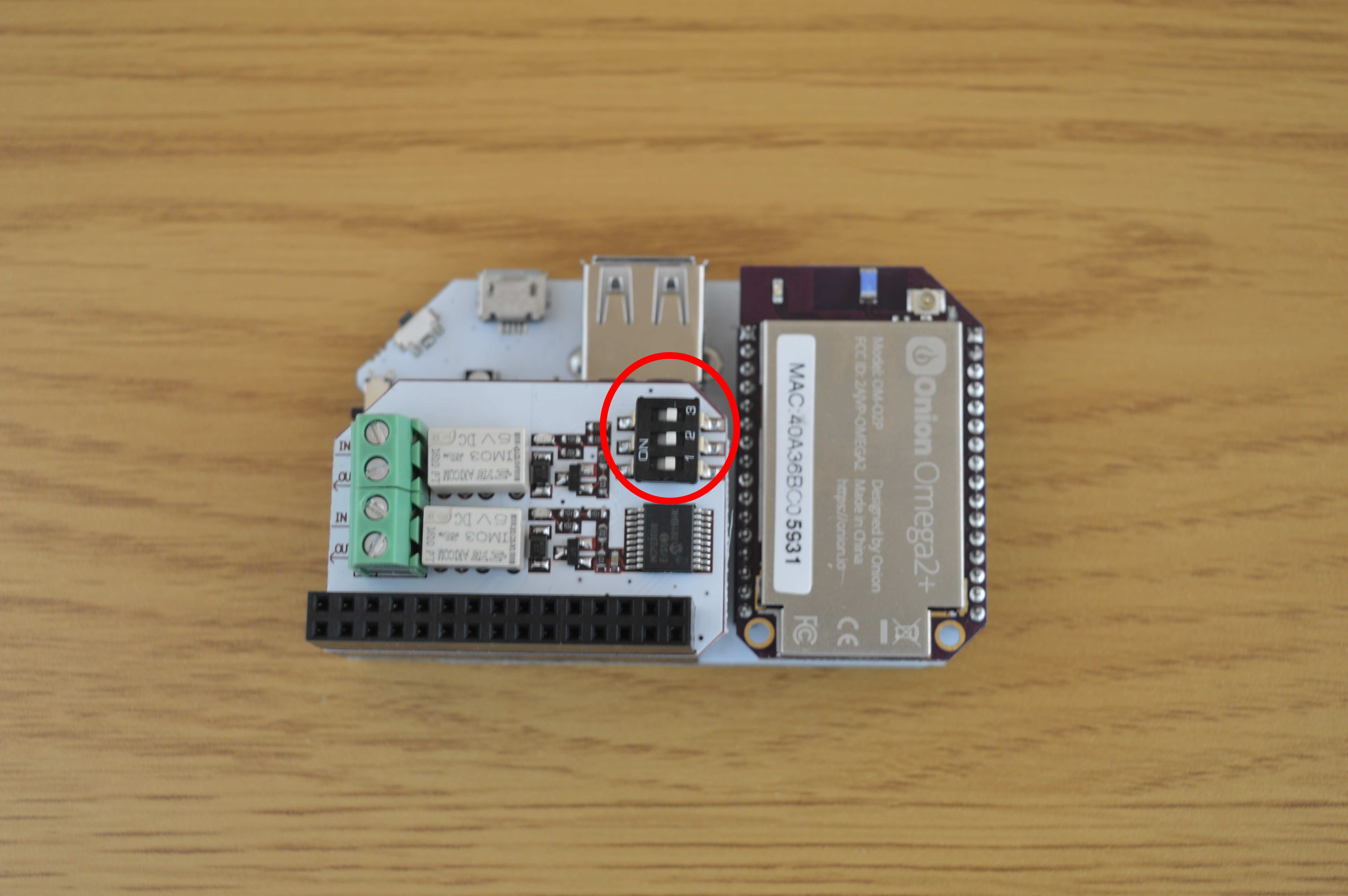
It has 3 switches that can be turned either ON or OFF. See the following table for the address values:
| Switch 1 | Switch 2 | Switch 3 | Binary Value |
|---|---|---|---|
| OFF | OFF | OFF | 000 |
| OFF | OFF | ON | 001 |
| OFF | ON | OFF | 010 |
| OFF | ON | ON | 011 |
| ON | OFF | OFF | 100 |
| ON | OFF | ON | 101 |
| ON | ON | OFF | 110 |
| ON | ON | ON | 111 |
The I2C addresses corresponding to the different switch positions are shown below:
| I2C Device Address | Switch Binary Setting |
|---|---|
| 0x27 | 000 |
| 0x26 | 100 |
| 0x25 | 010 |
| 0x24 | 110 |
| 0x23 | 001 |
| 0x22 | 101 |
| 0x21 | 011 |
| 0x20 | 111 |
Mechanical Drawings
We’ve made available a detailed diagram of the dimensions and geometry of the Relay Expansion.
Using the Relay Expansion
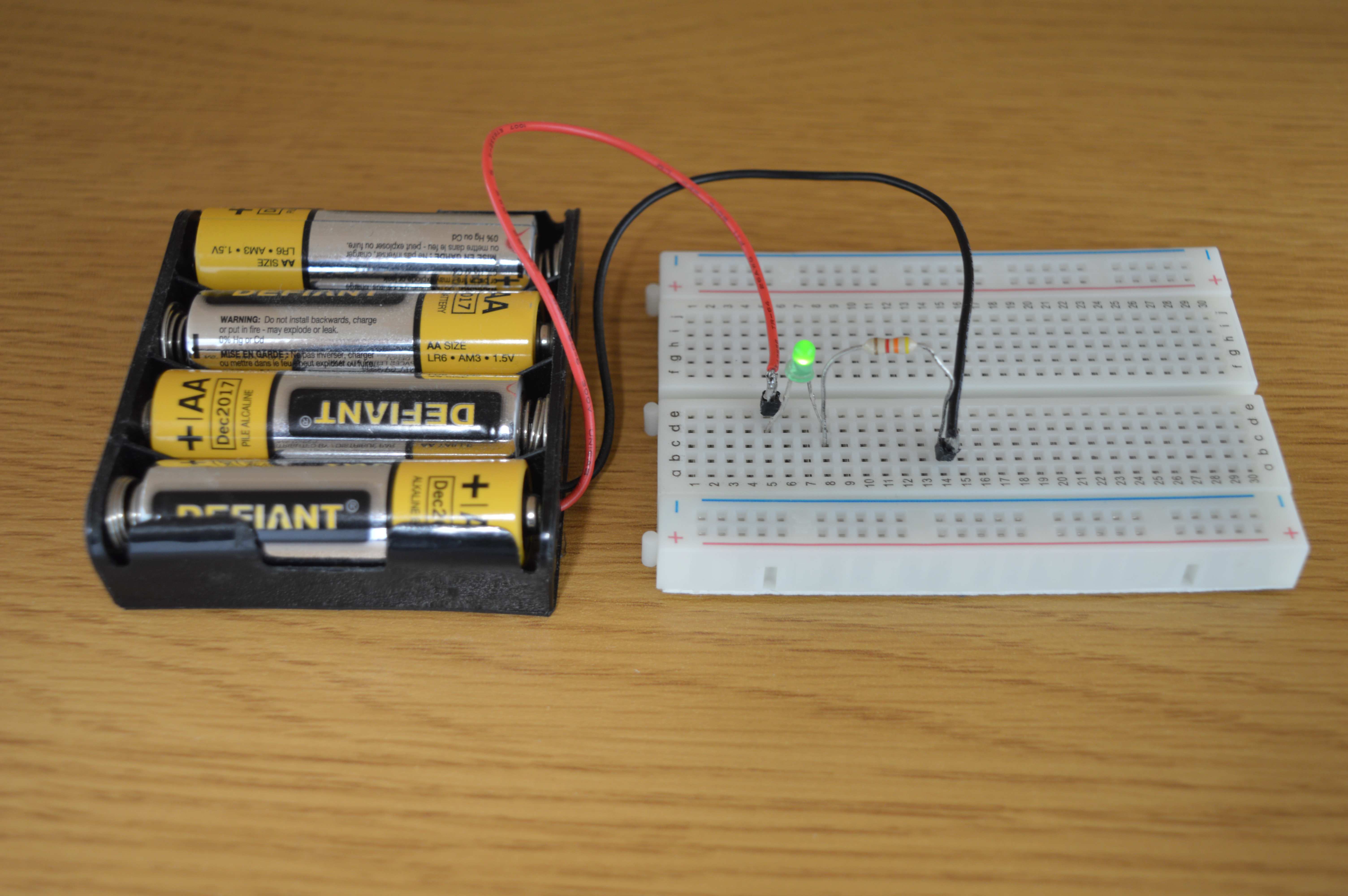
Consider this LED circuit:

We can build this circuit without the switch:
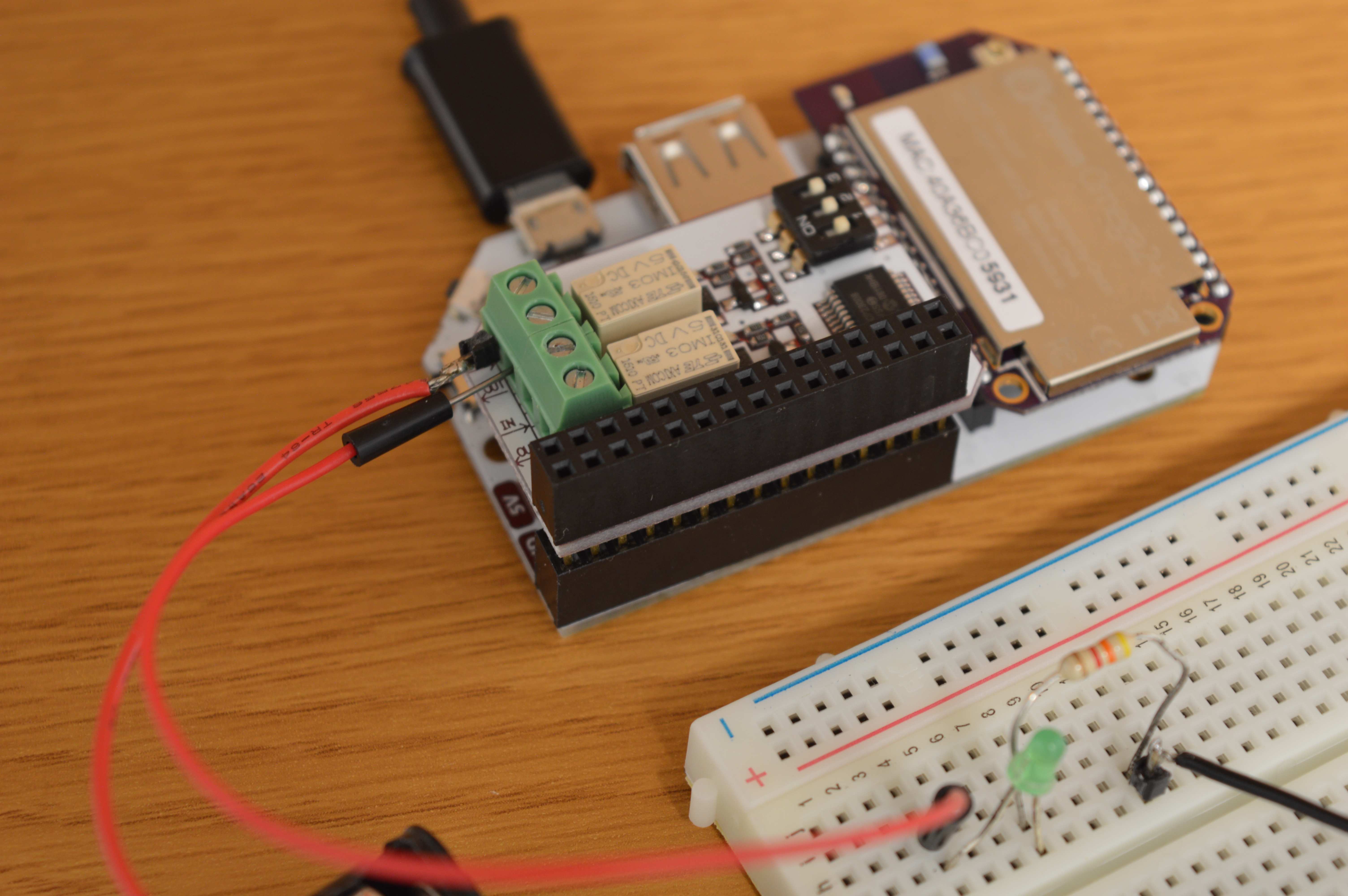
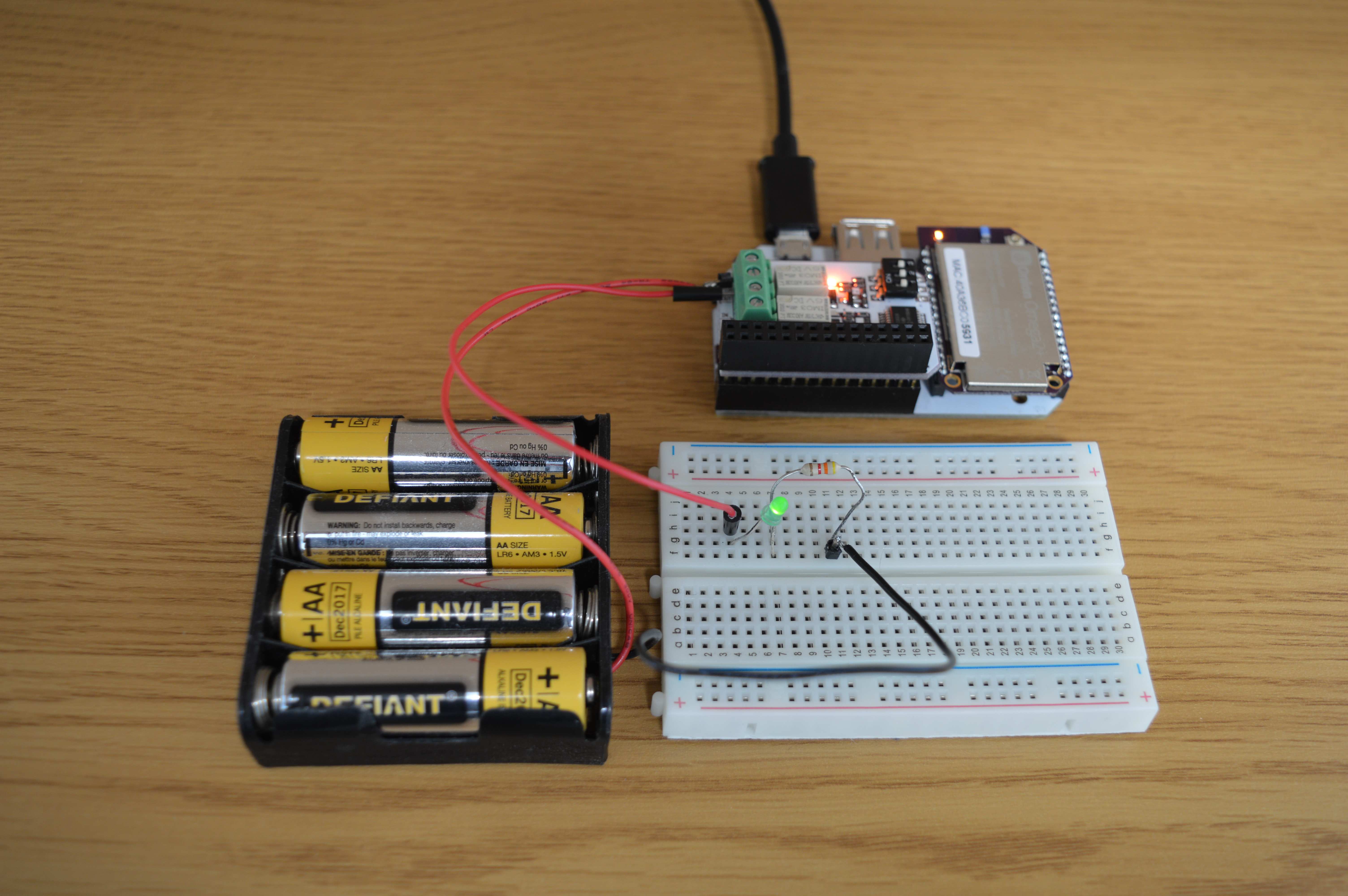
Next, we will add the Omega and Relay Expansion to act as the switch:
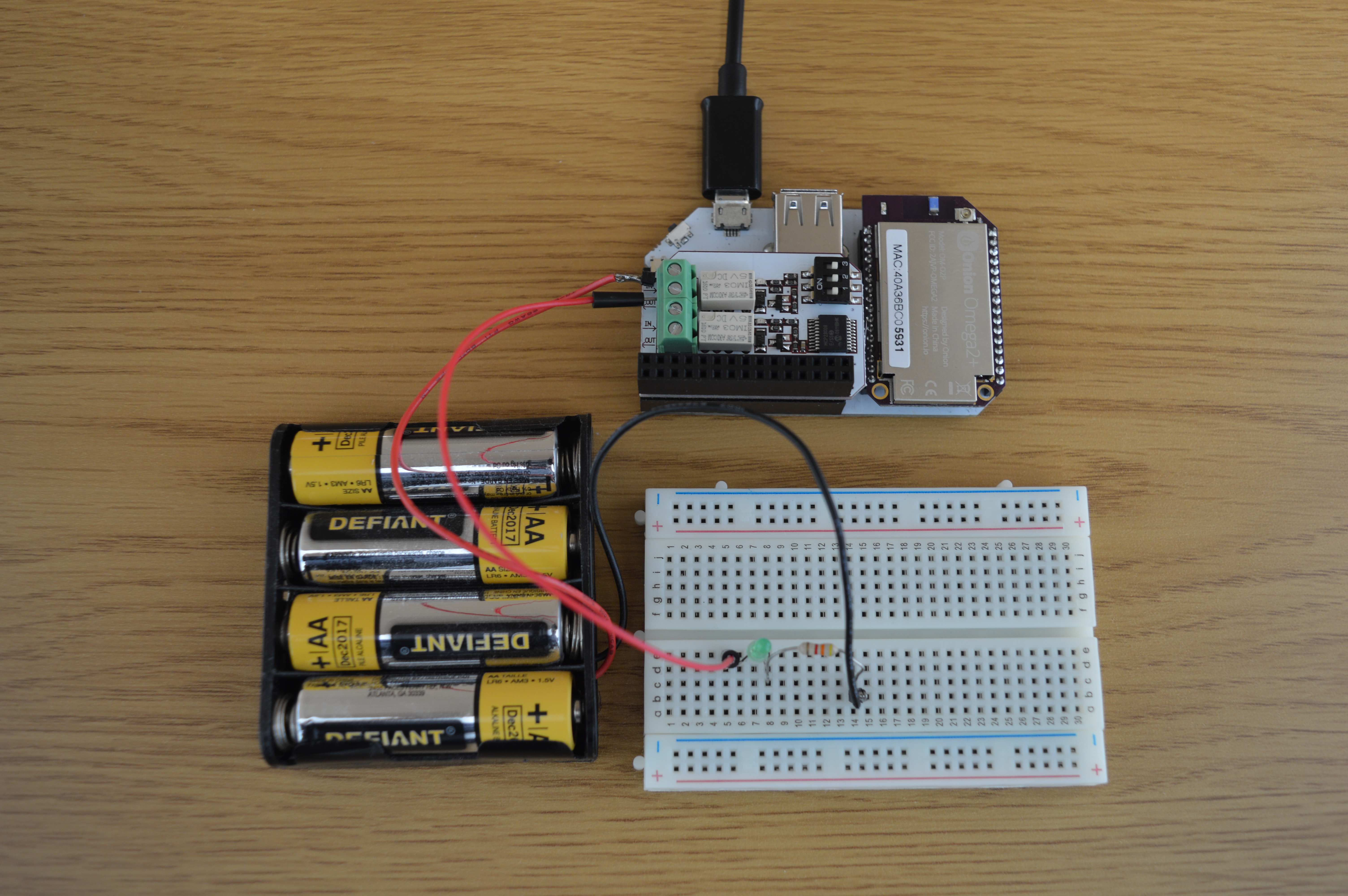
The positive lead of the battery pack is connected to the port labelled IN on the Expansion. A jumper wire is connected from the OUT port back to the circuit. Since the Relay is OFF, the switch is off and no current is passing through the LED:
When we turn the relay on, it acts as a closed switch, allowing current to flow through the LED:
The Relay Expansion can be used to control almost any type of external circuit, such as a lamp, coffee maker, or even your garage door!
Read our guide to using the Relay Expansion to learn how to control it using software.