Arduino Dock 2
The Arduino Dock 2 is our supercharged version of an Arduino Uno R3 board. These two boards share the same microcontroller, the ATmel ATmega328P microcontroller (MCU), and have identical pin layouts. This allows you to use any Arduino shields that you’ve used with the Arduino Uno R3 with the Arduino Dock and the Omega.
The Omega can program the microcontroller while connected to the board. This means you can wirelessly connect to the Omega, and then program the MCU for a wireless Arduino experience!
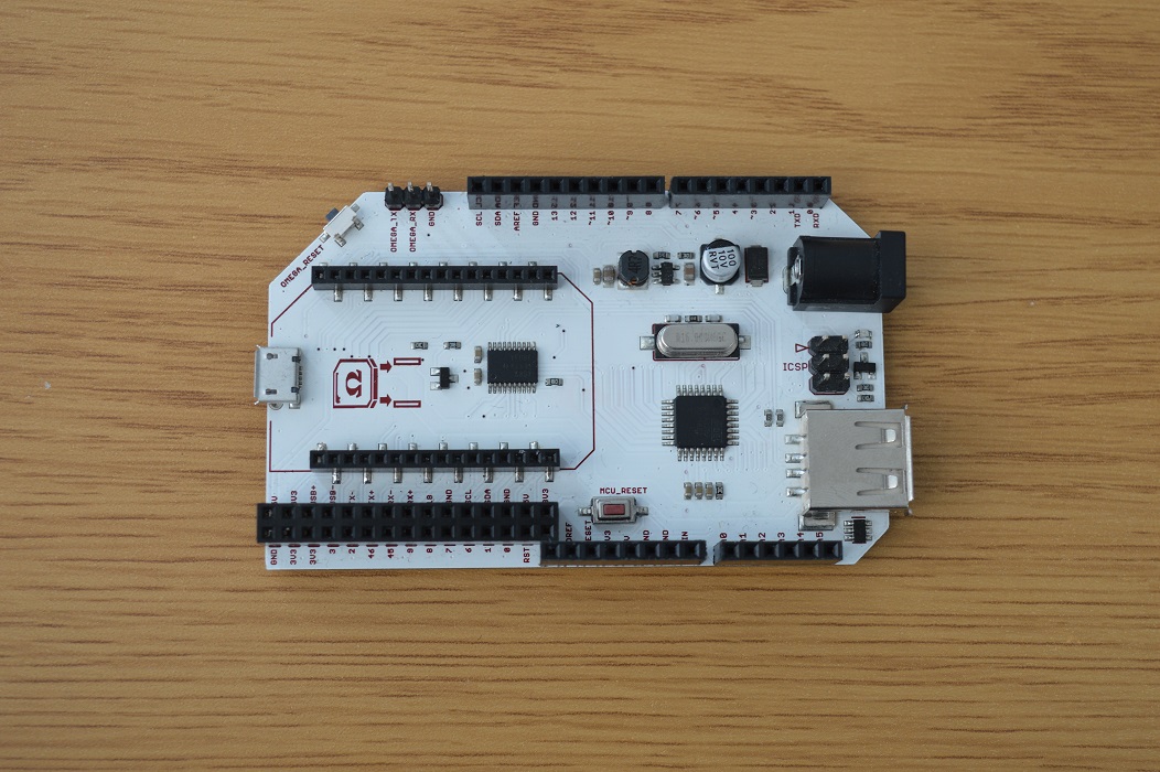
The Hardware
The Arduino Dock includes an In-Circuit Serial Programming (ICSP) header to break out the SPI pins which can be used to program the Arduino Dock’s microcontroller with an external programmer. Additionally, there is a USB-host port that is connected to the Omega which can be used for any sort of USB type application.
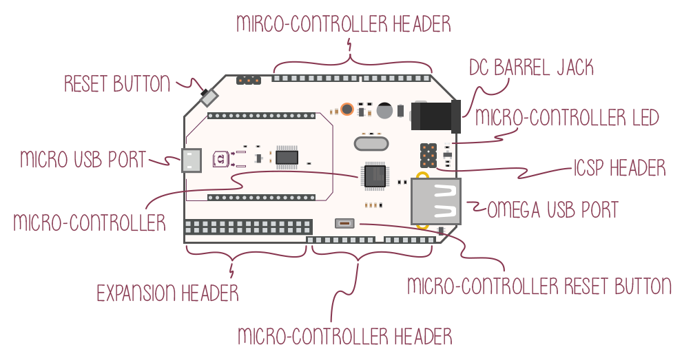
You can power the dock using a microUSB connection, or using the DC Barrel jack.
Connecting an Omega
To connect an Omega to the Arduino Dock, line up the Omega’s edges with the purple lines on the Arduino Dock’s as demonstrated below:
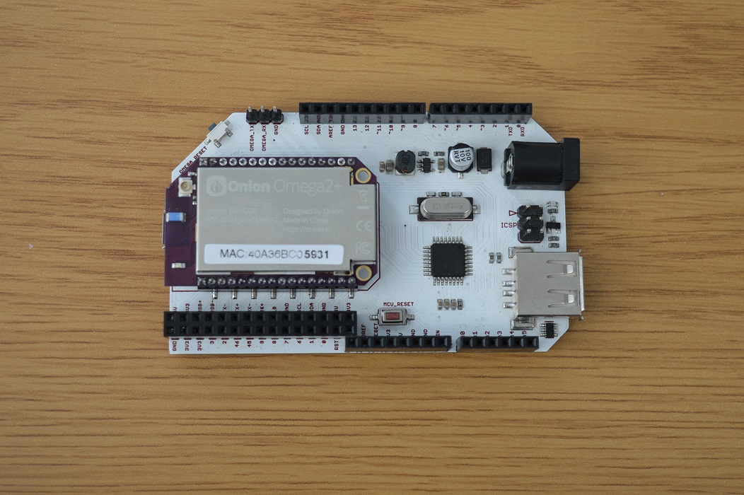
Make sure your Omega is pushed all the way down as demonstrated in the picture below:
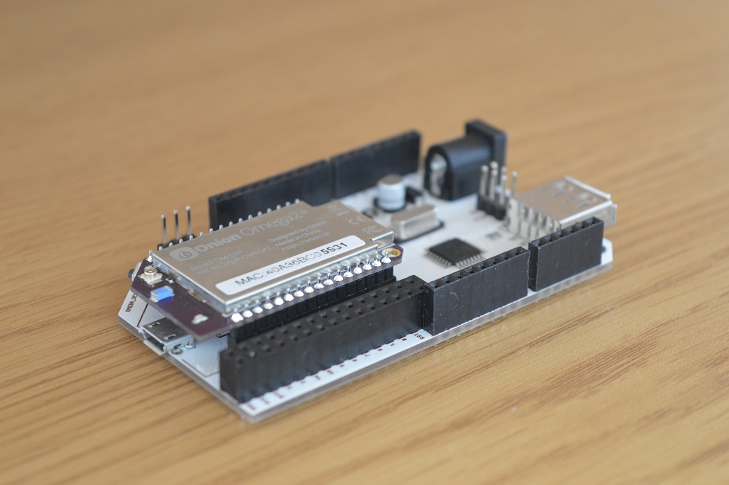
You may need to line up the pins with the holes before pressing the Omega into the Dock.
The Expansion Header
The Expansion Header is a convenient tool that gives you easy access to the Omega’s GPIOs, and allows you to connect Onion Expansions directly. The Expansion Header is labelled to show you what GPIO is connected to each header.
It follows the same layout as the Expansion Header found on the Expansion Dock and Power Dock.
Note:If you own an Omega2 or Omega2+ and intend to use the PWM expansion with a DC power supply, please take note there is likely to be a short circuit between the barrel jack and the metal case of the Omega itself. We recommend inserting a thin plastic sheet between the expansion and the omega to break this short. For more information, see the PWM Expansion article.
The pinout diagram below shows the Expansion Header’s connections and the possible multiplexing options:
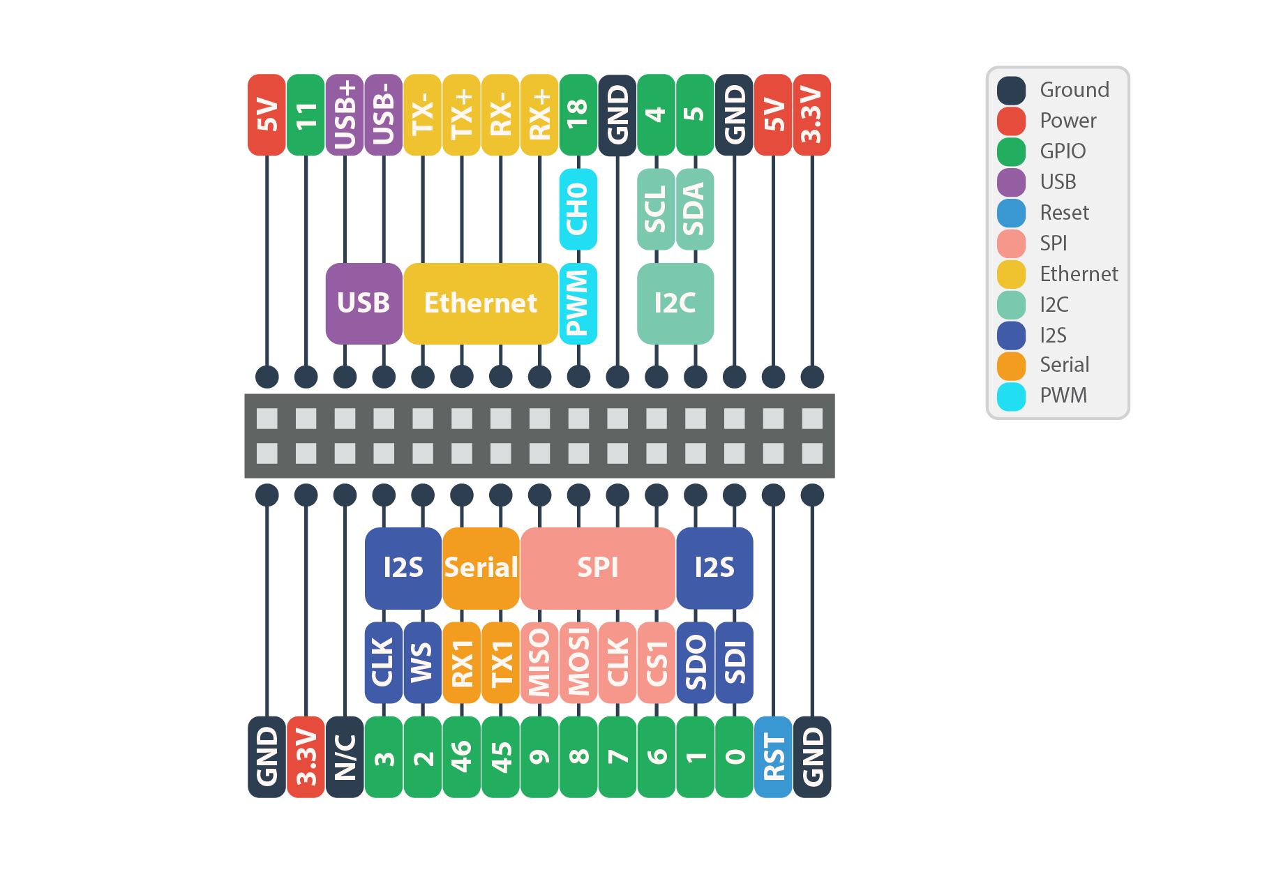
By default, the Serial, SPI, and I2C pins implement these communication protocols and cannot be used as GPIOs. Similarly, the I2S and PWM pins are set to GPIO mode by default.
To learn more on changing the functionality of the Omega’s pins, see the Multiplexing GPIOs section of our article on the Omega’s GPIOs.
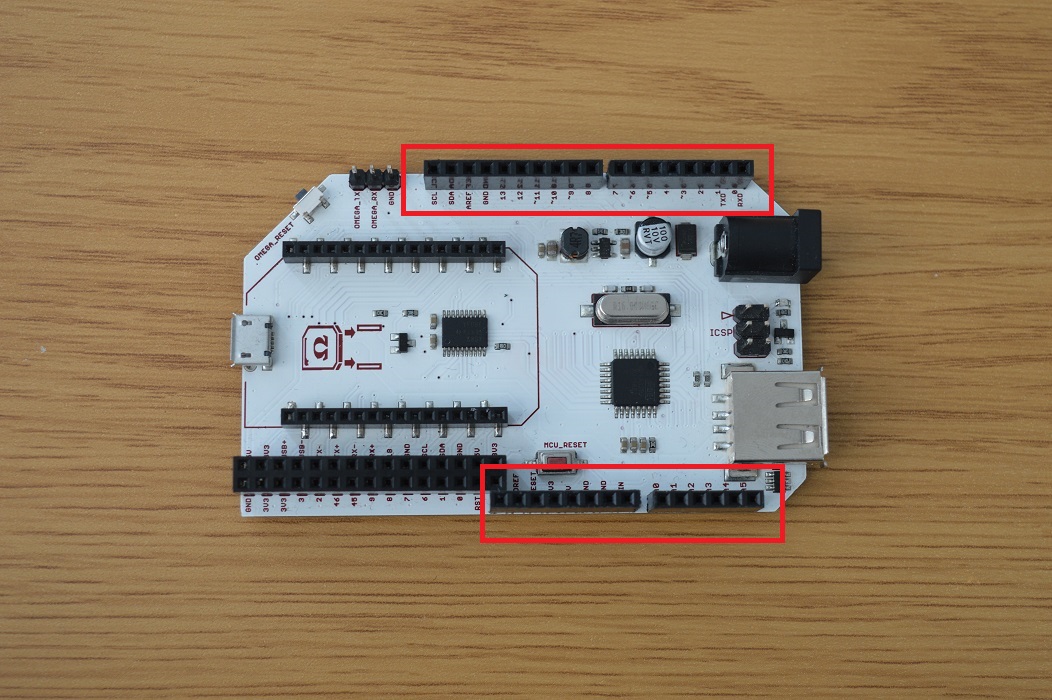
The ATmega Headers
The ATmega headers are a breakout of the ATmega’s pins. They are arranged and spaced in the exact same way as an Arduino Uno R3, so all your Arduino Shields are compatible. These pins are also labelled for your convenience.
Note: Remember that the ATmega runs on 5V, and therefore it reads 5V as logical high.
The MicroUSB Port
The MicroUSB Port is used to supply power to the Arduino Dock, which in turn supplies power to the Omega and the ATmega328P chip.
The MicroUSB Port receives 5V power and uses it directly to power the ATmega328P chip. The Dock comes equipped with a voltage regulator to step the voltage down to the required 3.3V for the Omega.
No USB-to-Serial
There is no USB-to-Serial Chip on the Dock. This means that you will not be able to connect to the Omega serially over the Micro-USB port.
You can still connect to your Omega’s terminal with SSH, you can learn how to do that in this guide to connecting to the Omega.
DC Barrel Jack
The DC barrel jack may also be used to provide power to the Omega using a DC power adapter. We recommend any DC power supply that provides 5V and at least 0.5A. It is safe to use power supplies that provide more than 0.5A at 5V.
Note that the Arduino Dock’s DC barrel jack should only be used with 5V DC power supplies. If a higher voltage is used, your Omega and Arduino Dock have a high chance of being damaged!
Omega USB Port
The Omega’s USB Port can be used to connect to all sorts of devices, namely a USB storage device to extend the storage space of your Omega. The USB port supports USB 2.0, and is a type A connector.
Omega to ATmega MCU Connections
The Arduino Dock is designed to make the on-board microcontroller the Omega’s helper and co-processor. So it was important to include a few key connections between the Omega and the microcontroller.
Since the microcontroller operates at 5V and the Omega operates at 3.3V, the Arduino Dock features a 3.3V to 5V Logic Level converter for all connections between the microcontroller and the Omega. This allows each device to operate at it’s own voltage but still gives them the ability to understand each other.
The table below shows the connections between the Omega and the ATmega Microcontroller:
| Omega Pin | ATmega Pin |
|---|---|
| UART1 | Serial Pins |
| I2C | I2C |
| GPIO 15 | SPI SCK |
| GPIO 16 | SPI MOSI |
| GPIO 17 | SPI MISO |
| GPIO 19 | Reset |
The purposes of these connections are covered in the subsections below.
UART Connection
The UART connection is used to provide two-way communication between the Omega and the ATmega MCU. The ATmega’s serial port is connected to the Omega’s UART1 serial port.
See the article on Communicating with Serial Devices for more info.
I2C
The I2C connection provides I2C connectivity between the Omega and the ATmega. In most cases, the Omega is set up as the master, and the ATmega as the slave.
This is useful when using 5V I2C devices. Plug them into the ATmega’s I2C pins and the Omega will be able to read them thanks to the on-board logic level shifter.
See the article on Communicating with I2C Devices for more info.
SPI and Reset Connection
The four SPI connections are used to upload the ATmega with sketches using your Omega. See the article on Flashing the Arduino Dock’s Microcontroller for more info.
The reset connection is used to reset the ATmega chip. This can be done using the reset button, or using the Omega’s GPIO 19.
Mechanical Drawings
We’ve made available a detailed diagram of the dimensions and geometry of the Arduino Dock 2.
Using the Dock
The Arduino Dock 2 is loaded with features that allow you to use your Omega with the ATmega chip with ease. You can program or reset the micro-controller using the Omega’s GPIOs, and even connect to the ATmega’s serial port using the Omega’s UART.
Programming the Arduino Micro-Controller
Follow the steps in our Flashing the Microcontroller to learn how to upload sketches (programs) to the Arduino micro-controller onboard the Arduino Dock.
Communicating over UART
The easiest way to get the Arduino Dock MCU and Omega communicating is through serial. There are no fancy protocols, just data being sent back and forth. It’s important to remember that the ATmega’s serial is connected to UART1 on the Omega.
Take a look at our Communicating with Serial Devices article for ideas on how to get your Omega communicating with the Arduino Dock’s microcontroller!
Communicating with I2C
The Arduino Dock 2 connects the microcontroller’s I2C lines to that of the Omega, effectively, adding the microcontroller as a slave to the Omega’s I2C bus.
Take a peek at our Communicating with I2C Devices article for more information on I2C and how the Omega can interact with I2C devices. On the microcontroller side, the Wire Library can be used to facilitate I2C communication.