Using the Relay Expansion
The Relay Expansion allows you to control two relay modules. Relays are basically electronically operated switches, enabling the Omega’s low power circuits to control other, potentially high power circuits.
You can learn more about the technical specifications of the Relay expansion in our Relay Expansion hardware overview
Example Circuit
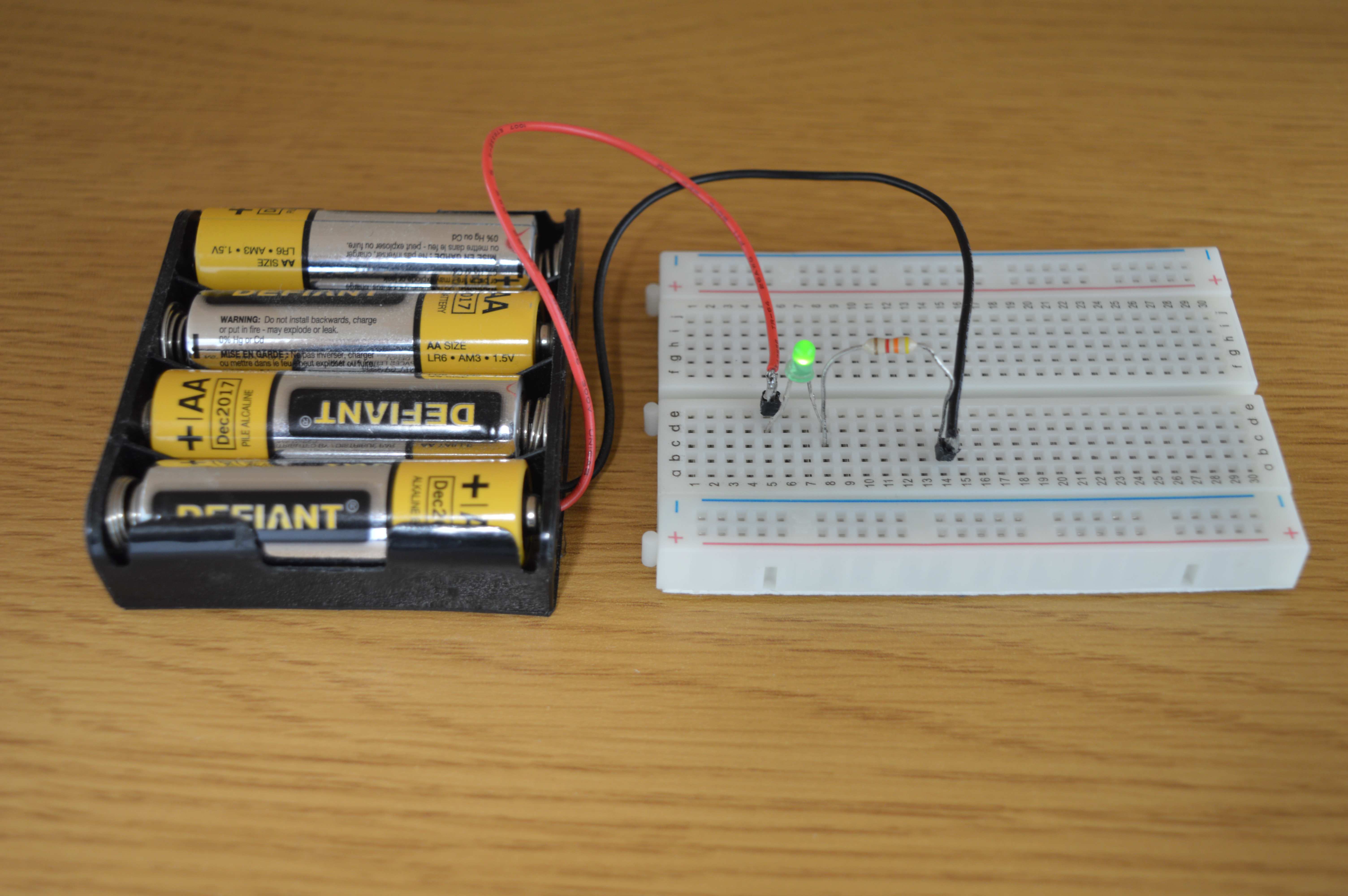
Since relays are essentially switches, they can be used as switches in other circuits. Consider this LED circuit:

We can build this circuit without the switch:
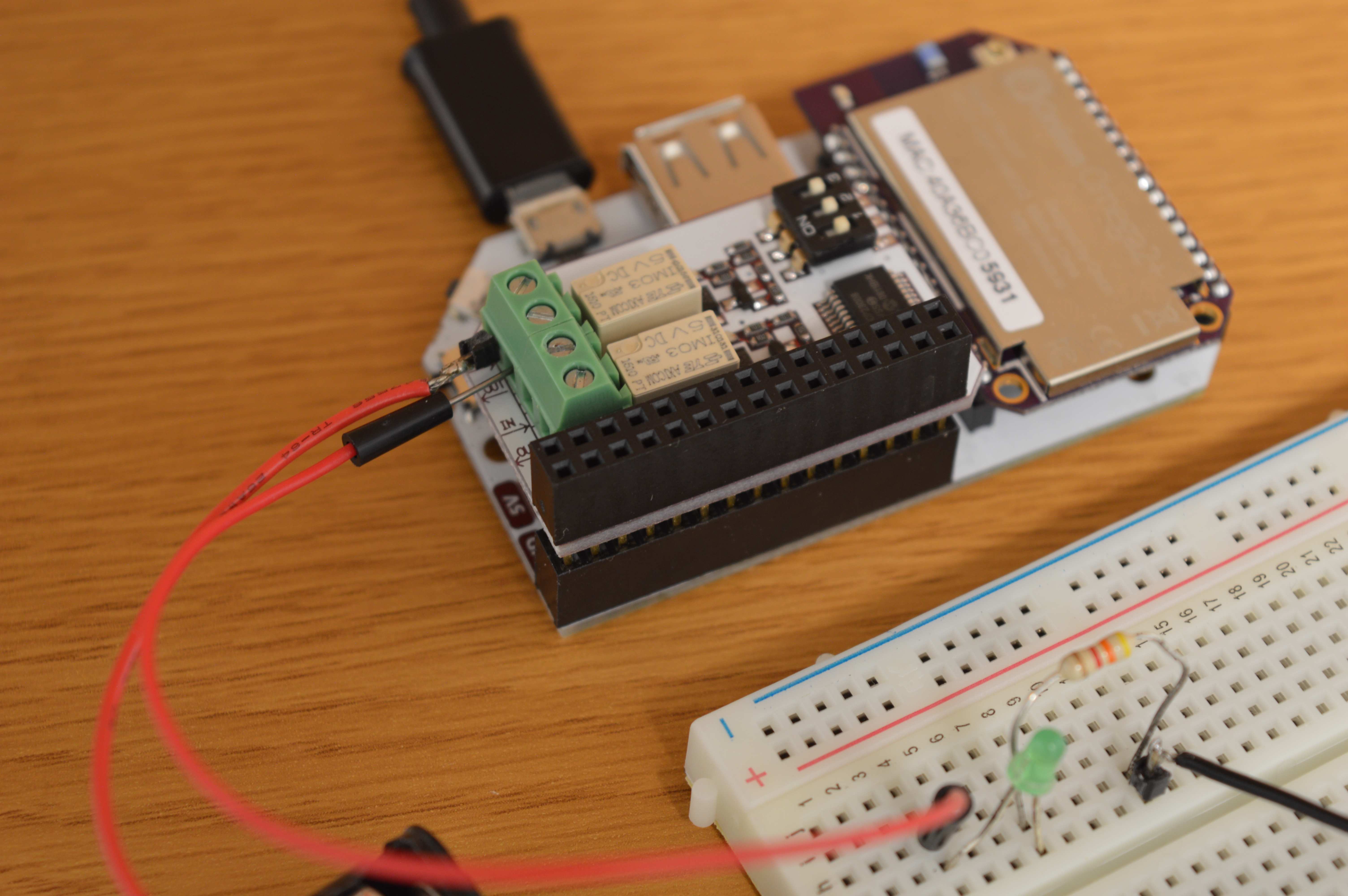
Next, we will add the Omega and Relay Expansion to act as the switch:
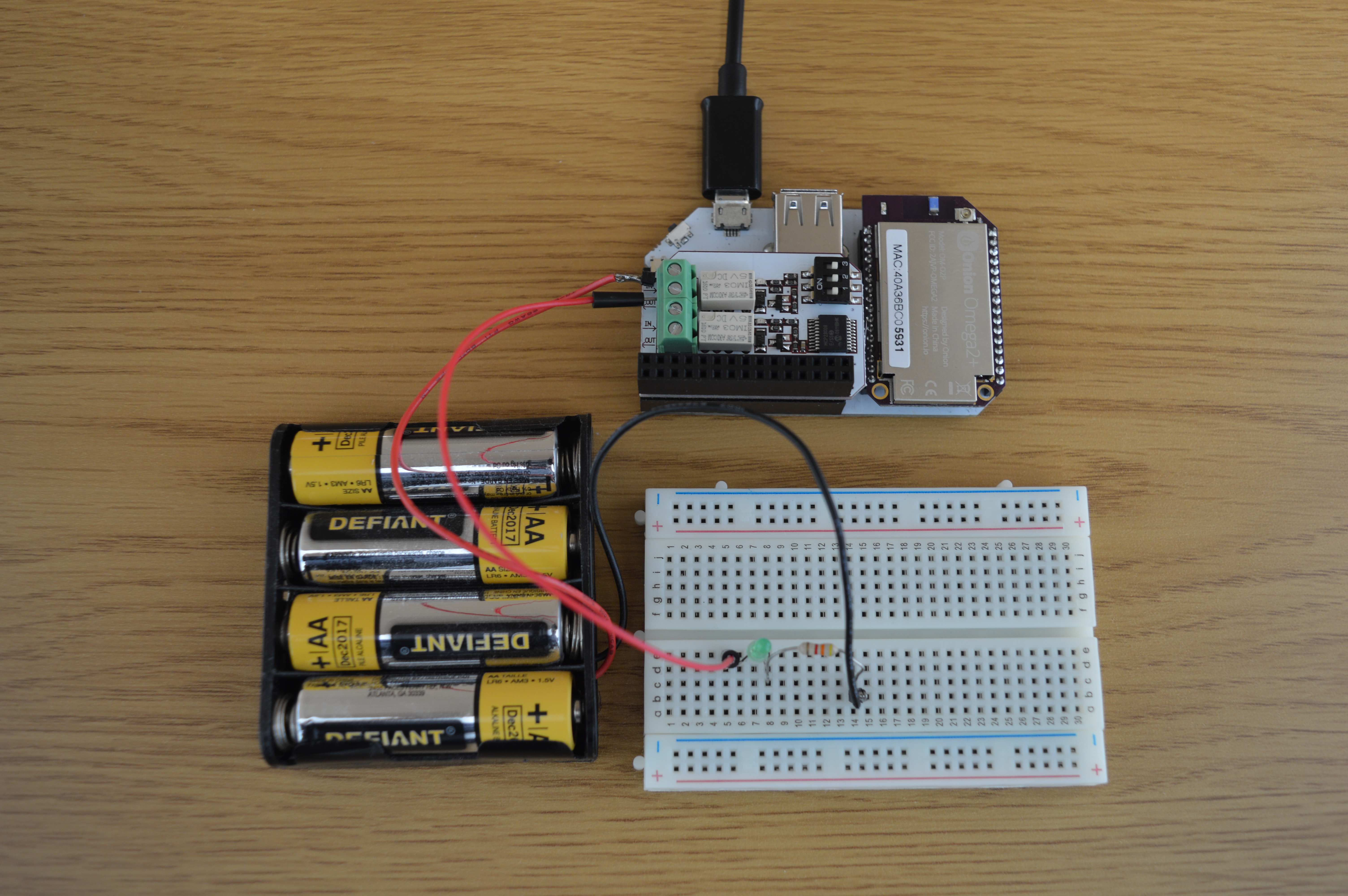
The positive lead of the battery pack is connected to the port labelled IN on the Expansion. A jumper wire is connected from the OUT port back to the circuit. Since the Relay is OFF, the switch is off and no current is passing through the LED:
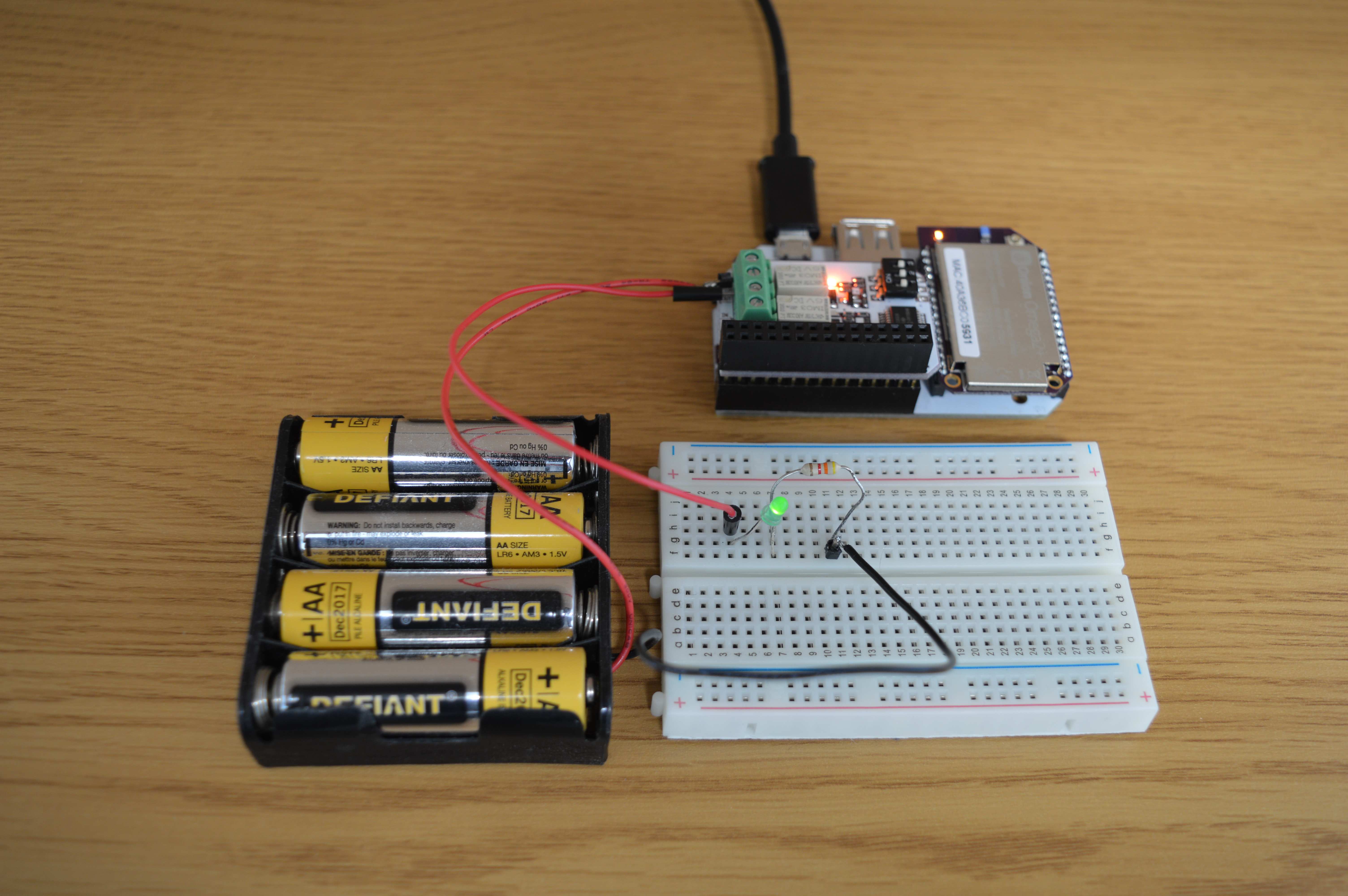
When we turn the relay on, it acts as a closed switch, allowing current to flow through the LED:
The Relay Expansion has two modules, so it is possible to control two different circuits with a single Relay Expansion.
Using the Command Line
Make sure that your Omega has the latest firmware!
We’ve developed a command line tool called relay-exp will make controlling your relay expansion easy as pie. We’ve also developed both a C library and a Python module that allow you to develop your own programs to control the Relay Expansion!
This guide will focus on the command line tool. We’ve provided in-depth articles on the software libraries at the bottom of this page.
Command Usage
For a print out of the command’s usage, run it with just a -h argument:
relay-exp -hInitialization
After every power-cycle, the chip on the Relay Expansion must be initialized to correctly and safely control the Relay Modules. The driver application will automatically detect if initialization is required and perform the required sequence, so there is no need to run this command yourself.
However, you can still manually trigger the initialization. Run the following command:
relay-exp -iYou can run this on its own or in conjunction with any commands below.
By default, the relays will be OFF.
Relay Channels
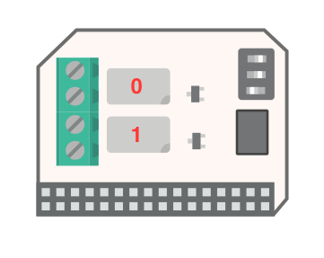
The Expansion has two modules. This guide will refer to them as RELAY0 and RELAY1, or as channels. The channels are labelled below:
Setting a Relay’s State
You can use this tool to program the relay’s states like so:
relay-exp <CHANNEL> <STATE>Let’s go over the arguments below:
<CHANNEL>-0or1forRELAY0orRELAY1respectively.<STATE>-0oroffto turn the relayOFF;1oronto turn the relayON
When the relay is OFF, it will act as an open switch, so any circuit connected to it will not be closed and will therefore be powered down. When it is ON, it is essentially a closed switch, so connected circuits will be powered on.
A few examples…
To initialize the chip and enable RELAY1:
relay-exp -i 1 1To disable RELAY1:
relay-exp 1 0To turn on RELAY0:
relay-exp 0 onControlling both Relays Simultaneously
You are also able to control both relays in a single command:
relay-exp all <STATE>As above, the state argument should be 0 or off to turn the relay OFF, or 1 or on to turn the relay ON, the only difference is that it will now affect both relays.
Some Examples:
Initializing the chip and turning all relays ON:
relay-exp -i all 1Turning all relays OFF:
relay-exp all offReading a Relay’s State
The tool also allows you to check the current state of the relay:
relay-exp read <CHANNEL>The channel argument should be either 0 or 1 for RELAY0 and RELAY1 respectively.
The output of the program will indicate if the relay is ON or OFF.
A few examples…
To read the state of RELAY0:
root@Omega-1302:~# relay-exp read 0
> Reading RELAY0 state: ON
To read the state of RELAY1:
root@Omega-1302:~# relay-exp read 1
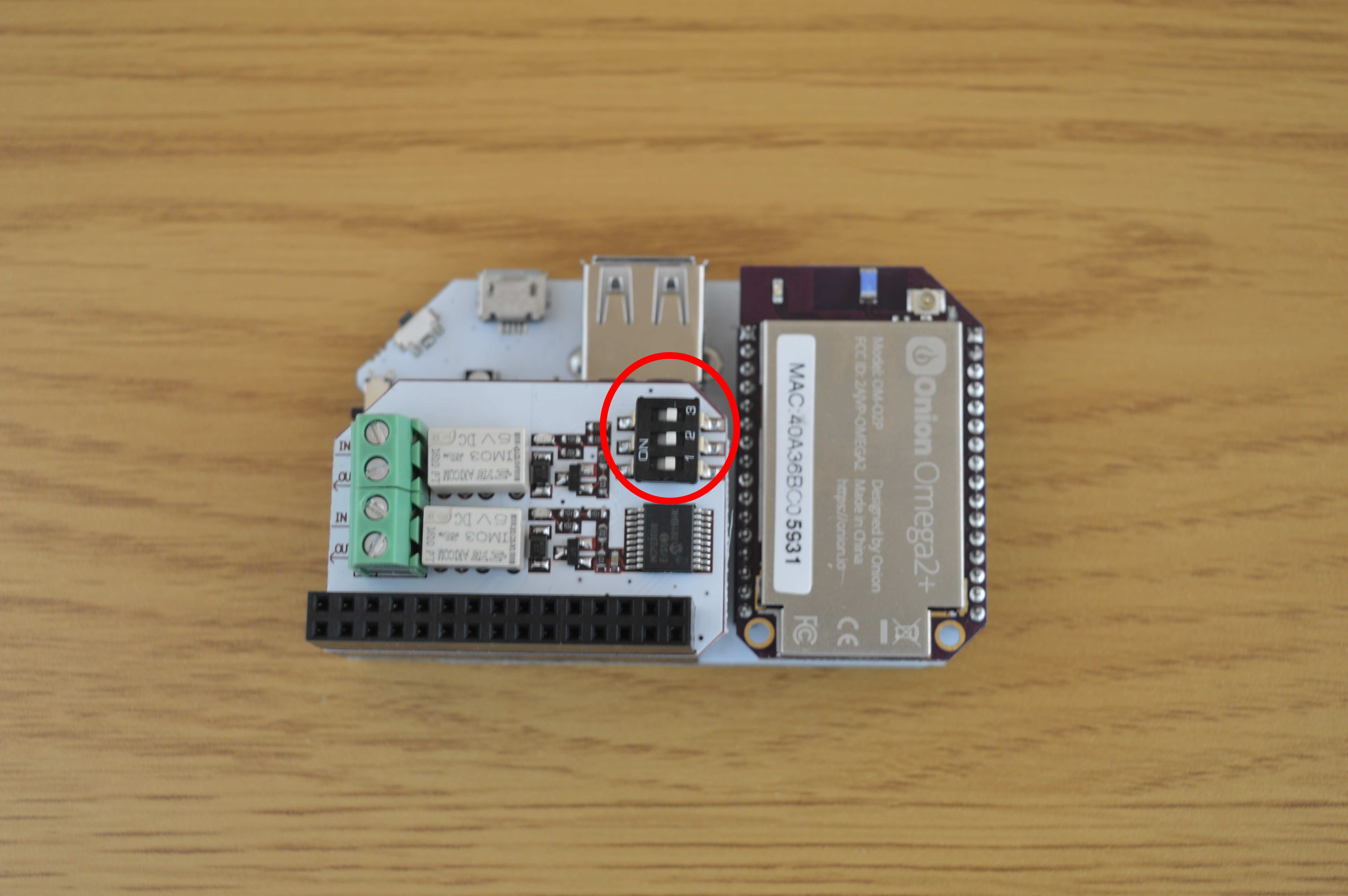
> Reading RELAY1 state: OFFUsing Multiple Relay Expansions by Changing the Dip-Switch Settings
The onboard dip-switch specifies the I2C address that the chip on the Relay Expansion declares to the I2C bus. A single Omega and Expansion Dock can control up to eight Relay Expansions if they all have different dip-switch configurations!
The relay-exp tool will need to know if the switch configuration has changed when programming the expansion:
relay-exp -s <BBB> <CHANNEL> <STATE>The new arguments are explained below:
-s- tells the program that you are providing the dip-switch value of the target Relay Expansion.<BBB>- a binary number representing the position of each switch.- If the switch is ‘OFF’, it is represented with a
0. - if the switch is ‘ON’, it is represented with a
1.
- If the switch is ‘OFF’, it is represented with a
The order is: Switch 1, Switch 2, Switch 3.
Follow this table:
| Switch 1 | Switch 2 | Switch 3 | Binary Value |
|---|---|---|---|
| OFF | OFF | OFF | 000 |
| OFF | OFF | ON | 001 |
| OFF | ON | OFF | 010 |
| OFF | ON | ON | 011 |
| ON | OFF | OFF | 100 |
| ON | OFF | ON | 101 |
| ON | ON | OFF | 110 |
| ON | ON | ON | 111 |
If all of the switches are off (000), the switch setting does not need to be specified and the command can be used as normal:
relay-exp <CHANNEL> <STATE>Some Examples:
The switches are set to on-off-on, setting RELAY0 to on:
relay-exp -s 101 0 onThe switches are set to on-on-on, setting RELAY1 to off:
relay-exp -s 111 1 0The switches are set to off-off-on, setting BOTH relays to on
relay-exp -s 001 all 1The switches are set to off-off-off, setting both relays to off
relay-exp all offI2C Address Mapping
If you’re curious about how the dip-switch settings affect the I2C device address of the Relay Expansion, then this table is for you:
| I2C Device Address | Switch Binary Setting |
|---|---|
| 0x27 | 000 |
| 0x26 | 100 |
| 0x25 | 010 |
| 0x24 | 110 |
| 0x23 | 001 |
| 0x22 | 101 |
| 0x21 | 011 |
| 0x20 | 111 |
Using the I2C Address Directly
If you don’t like dealing with the switch positions, you can use the I2C device address directly. Here’s how to do it:
relay-exp -a <ADDRESS> <CHANNEL> <STATE>The flags are explained below:
-a- tells the program to use the Expansion’s I2C address.<ADDRESS>- the I2C device address. It can be entered with or without the leading0x, so0x27or27will both work.
Some Examples:
For a device address of 0x23, set RELAY0 to on:
relay-exp -a 0x23 0 onFor a device address of 0x26, set RELAY1 to off:
relay-exp -a 26 1 0For a device address of 0x24, set all relays to on
relay-exp -a 0x24 all 1Using the Libraries
The C library and Python module will allow you to control the Relay Expansion with your own programs. See the guides below for more details: